182050 User manual.pdf - 第183页
semi automatic ',163(& 7,21 02'8/( 29(59,(: Software Version 07SP02 User Manual 7.9 V ision Window The video monitor displays what t he camera views, ( both board and s tencil). A Region of Intere st (RO…
semi automatic
',163(&7,21
02'8/(29(59,(:
7.8 User Manual Software Version 07SP02
If no image files are available, the display defaults to a standard board size
representation of the product file being printed.
By utilizing the mouse control, any area of the board representation selected by
the user roughly positions the camera to this area. Fine positioning is then
carried out by adjusting the X and Y scroll bars in the vision window. Existing
sites can easily be selected and adjusted using the mouse control.
NOTE
The vision window X and Y scroll bars are displayed only when movement of
the camera is allowed within GUI.
Site Colour Coding Sites displayed on the board representation are coloured according to their site
priority parameter setting, as detailed in the following table.
NOTE
The current selected site is displayed in black.
Operations Buttons The five operations buttons are sited underneath the representation of the
board and are used to perform functions on the board. These are:
• Load Image File - allows user to browse and select .bmp/.gbx image file.
• Unload Image File - allows user to unload the current .bmp/.gbx image file.
• Zoom In - zooms in to sites on the board representation.
• Zoom Out - zooms out from sites on the board representation.
• Fiducial Positions - show/hides board fiducial positions.
List of Devices and
Sites
The list of devices and sites created are displayed in an expandable and
collapsible form.
By selecting a site in the list, the camera moves to that site position and the
board representation site is highlighted with a camera position icon.
By selecting a device in the list, the device list automatically expands to show
all sites within that device. The first site within the list is selected and the camera
moves to that site position, the board representation site is highlighted with a
camera position icon.
NOTE
In this instance a device itself can never be selected.
Site Parameters The site parameters window enables the user to view the editable parameters
for the current site selected.
NOTE
The parameters in this display are view only.
X and Y Site
Coordinates
The X and Y site coordinates display is the current position of the mouse pointer
on the board representation.
Site Priority Display Colour
Every Cycle
Green
General
Yellow
Not Inspected
Blue
semi automatic
',163(&7,21
02'8/(29(59,(:
Software Version 07SP02 User Manual 7.9
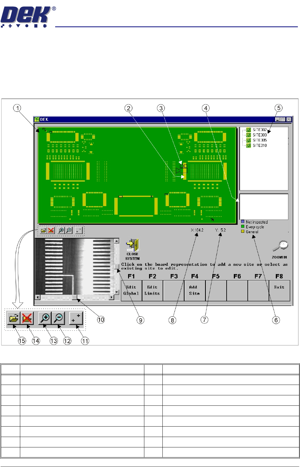
Vision Window The video monitor displays what the camera views, (both board and stencil). A
Region of Interest (ROI) box (red outlined), representing the current boundary
of the site is superimposed on both stencil and board displays.
When movement of the camera is allowed within GUI, scroll bars are displayed
in the vision window to enable fine positioning of the camera unit during site
setup.
Figure 7-5 GUI 2Di Interface (Bitmap File Representation)
Item Description Item Description
1 Board Representation (.bmp or .gbx image file) 9 Vision Window Y Scroll Bar (when available)
2 Inspection Site 10 Vision Window X Scroll Bar (when available)
3 Camera Position Icon 11 Show / Hide Fiducial Positions
4 Inspection Site Parameters 12 Zoom Out on Board Representation
5 Site List 13 Zoom In on Board Representation
6 Site Priority Guide 14 Unload .bmp or .gbx Image file
7 Site Y Coordinates (current mouse position) 15 Load .bmp or .gbx Image file
8 Site X Coordinates (current mouse position)
semi automatic
',163(&7,21
',163(&7,216(783
7.10 User Manual Software Version 07SP02
2D INSPECTION SETUP
Preparation For 2D Inspection functionality the machine requires 2D Inspection in set
preferences to be set to enabled. Carry out the following procedures:
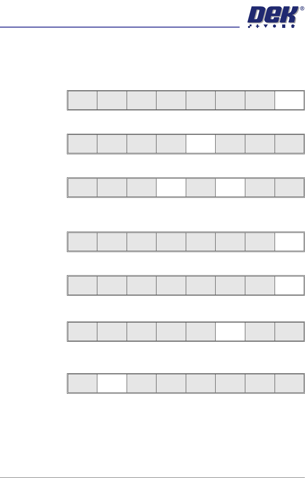
Set Preferences 1. Select Maint.
2. Select Set Prefs.
3. Using the Next and Incr keys, set 2D Inspection to Enabled.
4. Select Exit. The message ‘Printer configuration data file saved’ is
displayed in the message prompt bar above the menu bar.
5. Select Exit.
Load Product File 1. Select Setup.
2. Select Load Data. The message ‘Use keyboard to action product
search’ is displayed in the message prompt bar above the menu bar.
The Load Data File window appears.
Run
Open
Cover
Paste
Load
Clean
Screen
Setup Monitor Maint.
Calibrat
Pressure
Calibrat
Offset
Calibrat
Vision
House
Keeping
S e t
Prefs
Diagnost
Te st
Cycles
Exit
Next Previous Incr. Decr. Exit
Next Previous Incr. Decr. Exit
Calibrat
Pressure
Calibrat
Offset
Calibrat
Vision
House
Keeping
Set
Prefs
Diagnost
Te st
Cycles
Exit
Run
Open
Cover
Paste
Load
Clean
Screen
Setup Monitor Maint.
Mode
Load
Data
Edit
Data
Setup
Squeegee
Change
Screen
Change
Tooling
Change
Language
Exit