182050 User manual.pdf - 第256页
semi automatic &21680$ %/(5(3/ (1,6+0 (176 352)/2: 8.48 User Manual Software Ve rsion 07SP02 5. Fit the cover to the under side of the ProFlow transfer head uni t. 6. Release the l atch on the front of t he pressure…
semi automatic
&21680$%/(5(3/(1,6+0(176
352)/2:
Software Version 07SP02 User Manual 8.47
Retention System Replacement
Due to wear over prolonged periods, it is necessary to replace the wiper foils
and skis. An obvious indication of blade deterioration is print medium left
deposited on the screen after a print cycle, an example of this indication is
shown in the figure below.
Figure 8-1 Example of ProFlow Wiper Wear
Replace the wipers and skis as follows:
WARNING
SOLDER PASTE AND SOLVENTS. WHEN USING OR HANDLING ANY SOLDER
PASTE OR SOLVENT FORMULATION THE MANUFACTURERS’ RECOMMEND
SAFETY PRECAUTIONS MUST BE STRICTLY ADHERED TO.
WARNING
PROTECTIVE CLOTHING. APPROVED PROTECTIVE CLOTHING SHOULD BE
WORN BY SOLDER PASTE AND SOLVENT HANDLERS AT ALL TIMES TO
ELIMINATE FUME INHALATION, EYE CONTACT, SKIN CONTACT AND
INGESTION.
1. Press Setup (F6).
2. Press Setup ProFlow (F4).
3. Press Change ProFlow (F1). The message ‘Replace ProFlow Cover
then Close Cover and Press Continue’ is displayed.
4. Raise the printhead cover.
Run
Open
Cover
Paste
Load
Clean
Screen
Setup Monitor Maint.
Mode
Load
Data
Edit
Data
Setup
ProFlow
Change
Screen
Change
Tooling
Change
Language
Exit
Change
ProFlow
Load
Cassette
Prime
ProFlow
Exit
semi automatic
&21680$%/(5(3/(1,6+0(176
352)/2:
8.48 User Manual Software Version 07SP02
5. Fit the cover to the underside of the ProFlow transfer head unit.
6. Release the latch on the front of the pressure mechanism and raise the
mechanism forwards and upwards to engage the spring locking device.
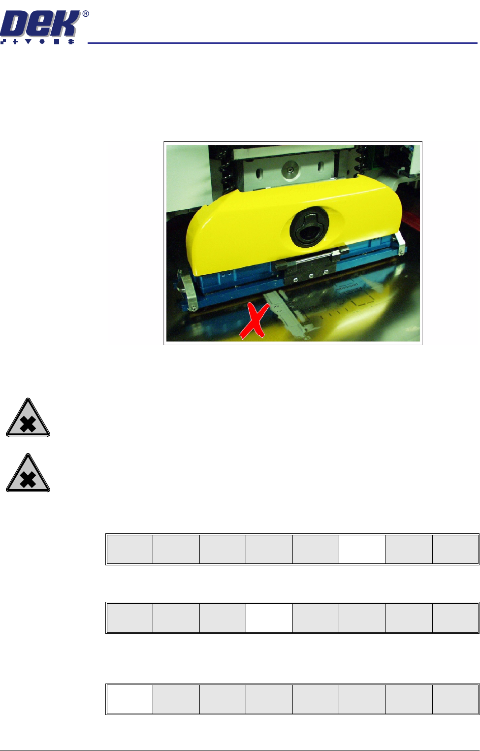
7. Open the locking clip securing the transfer head to the pressure mechanism
and carefully slide the transfer head out and away from the pressure
mechanism.
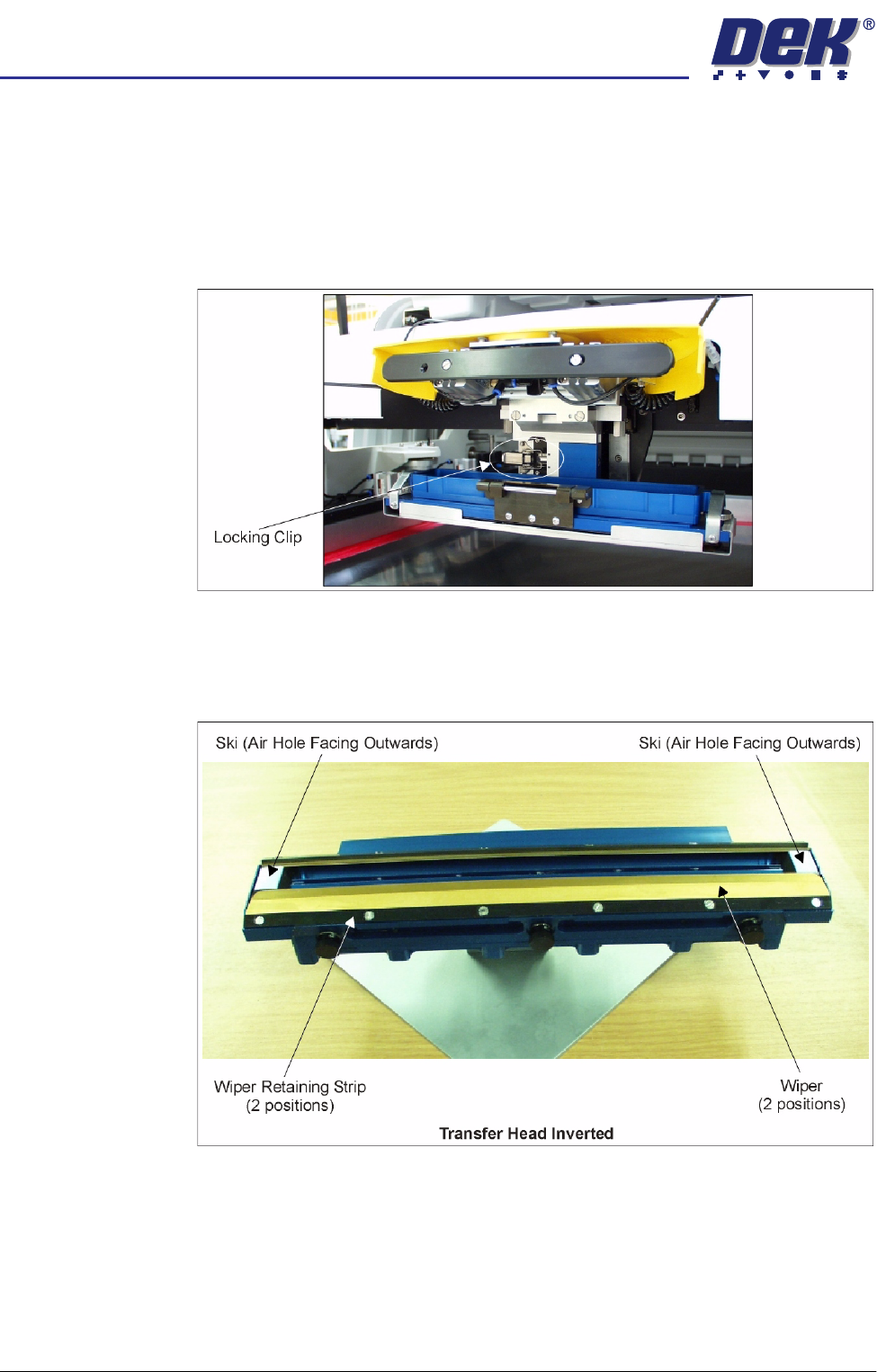
8. Invert the ProFlow transfer head and place onto the maintenance stand
(provided with the equipment).
9. Remove the cover from the ProFlow transfer head unit.
10. Carefully remove the wipers by loosening the six screws securing each
wiper retaining strip. Dispose of damaged wipers in accordance with local
authority guide lines.
11. Carefully remove both skis. Dispose of damaged skis in accordance with
local authority guide lines.
12. Prior to fitting replacement items ensure the area around the wipers and skis
is free from print medium.
semi automatic
&21680$%/(5(3/(1,6+0(176
352)/2:
Software Version 07SP02 User Manual 8.49
13. Fit replacement wipers into position ensuring both wipers are fully home
against the wiper securing screws.
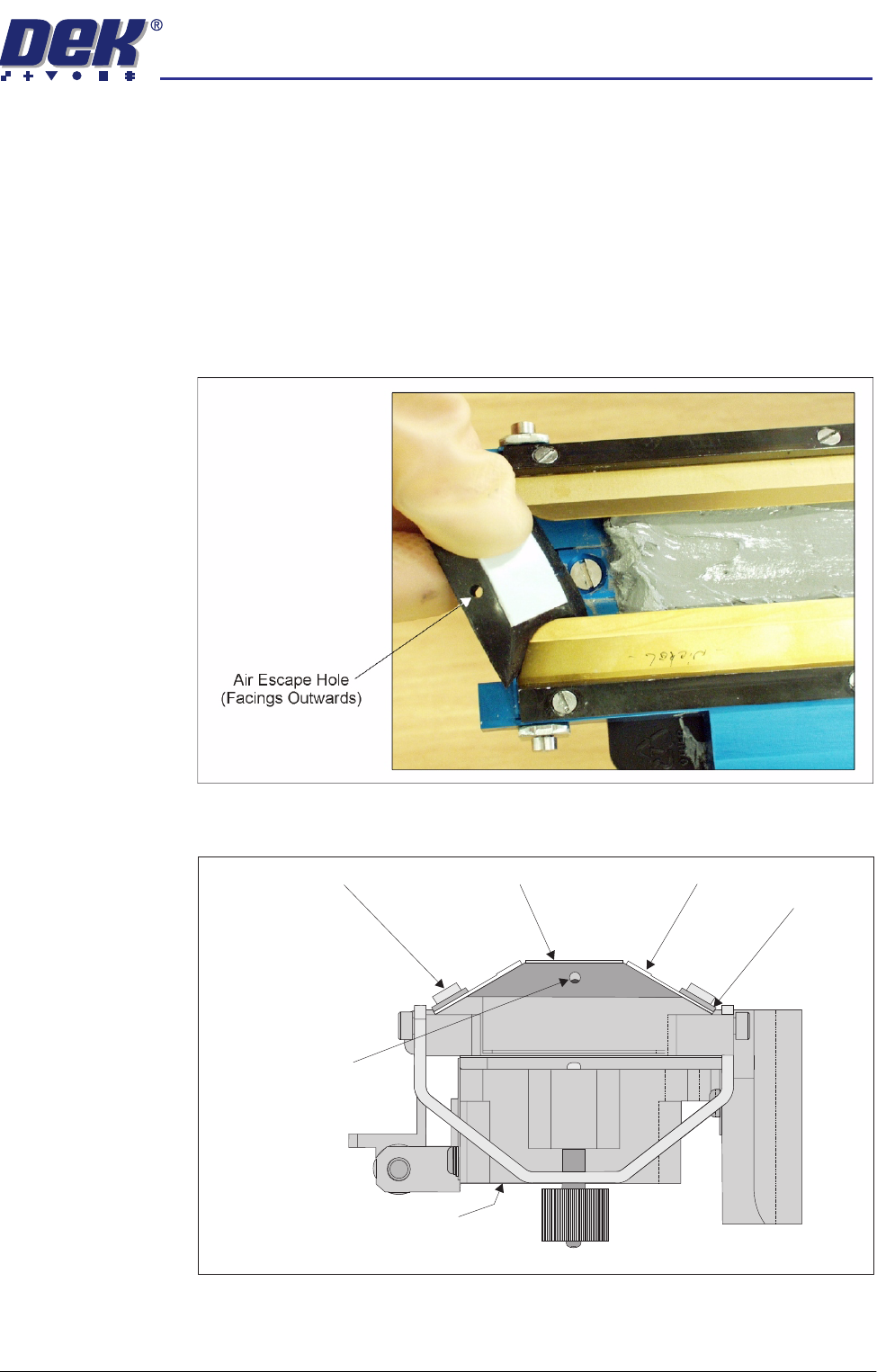
NOTE
If fitting stepped etched wipers, ensure that the stepped edge of each wiper
is facing outwards (wiper example in figure below refers).
14. Fully tighten the wiper retaining strip screws.
15. Slide each ski between the wipers until they are flush with the ends of the
wipers, (ensure the air escape hole on each ski faces outwards of the unit,
(figure below refers).
16. Fit the cover.
Ski
Ski Air Escape Hole
Wiper
ProFlow Transfer Head (Inverted)
Wiper
Retaining Strip
Inverted Transfer Head (End View)
Wiper Securing Screw