00197463-03_SM_CPP_Customer_EN.pdf - 第104页
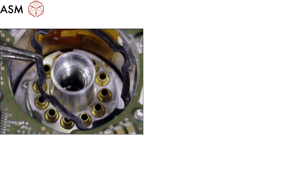
8 Screwed joint, silencer and holding circuit 8.4 Replacing the holding circuit 104 Service Manual SIPLACE Multistar (CPP / CPP M) 02/2018 Fig.178: Inserting the seal ► Put on the top seal. ► Follow the removal instruct…
8 Screwed joint, silencer and holding circuit
8.4 Replacing the holding circuit
Service Manual SIPLACE Multistar (CPP / CPP M) 02/2018 103
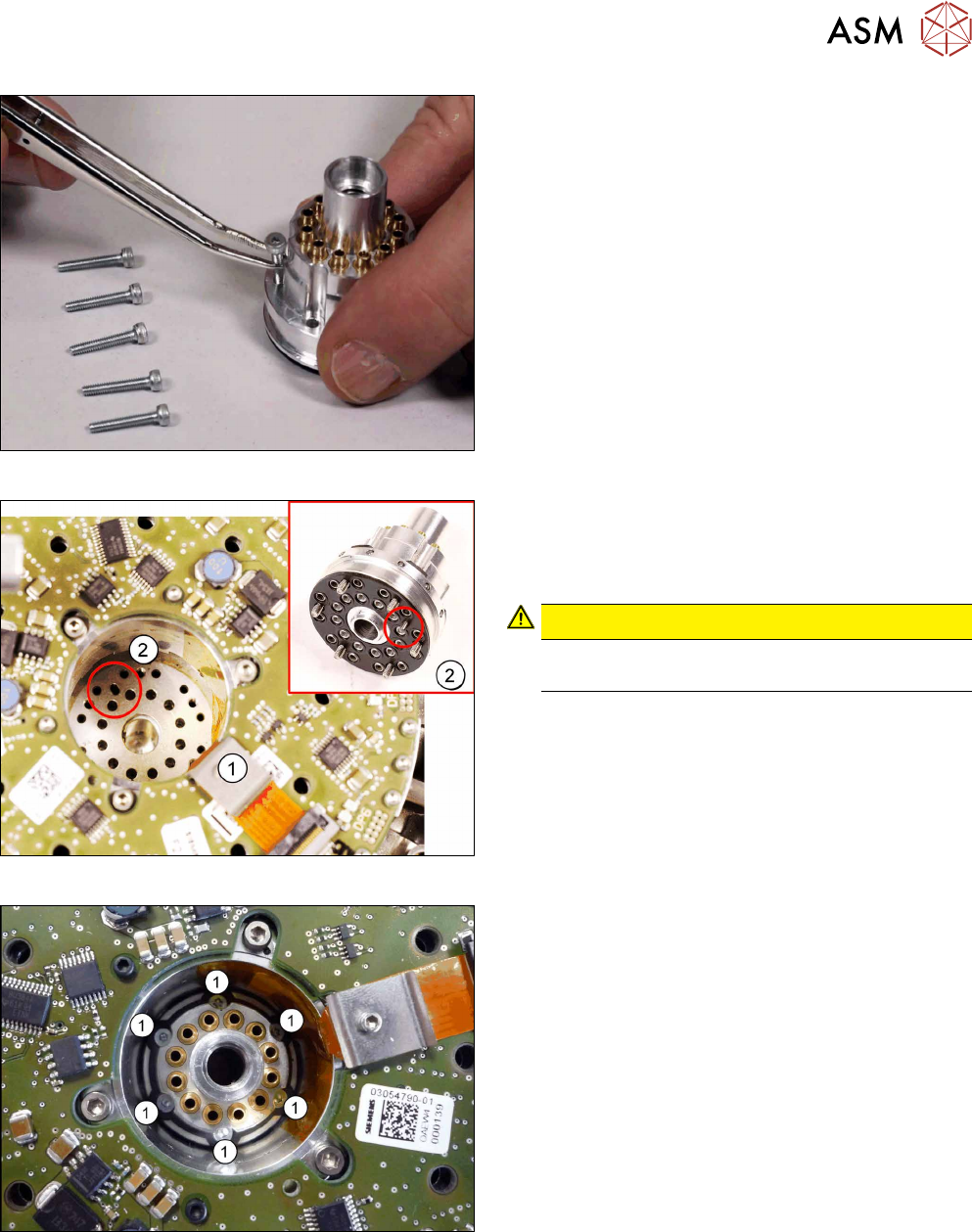
Fig.175: Holding circuit fastening screws
► Insert the six fastening screws into the holding
circuit.
Fig.176: Fitting the holding circuit
► Carefully insert the holding circuit. Pay attention
to the correct fitting position of the pin(2).
The holding circuit must engage properly when
inserted.
CAUTION!
Take care not to damage the Flexprint
cable (1).
.
Fig.177: Fixing the holding circuit
► Lightly tighten the fastening screws.
► Tighten the six screws fastening the holding cir-
cuit crosswise, with a torque of 0.2Nm.
8 Screwed joint, silencer and holding circuit
8.4 Replacing the holding circuit
104 Service Manual SIPLACE Multistar (CPP / CPP M) 02/2018
Fig.178: Inserting the seal
► Put on the top seal.
► Follow the removal instructions in reverse order for further installation.
Also observe the installation instructions in the following sections:
8.3.3 "Replacing the silencer" [}97]
8.2 "Replacing the screwed joint" [}94]
5.1 "Replacing the front plate [03061102-xx]" [}35]
► Observe in particular the torques specified!
9 Intermediate distributor and vacuum sensor
9.1 Replacing the KE Control Board ZV2 [03073355-xx]
Service Manual SIPLACE Multistar (CPP / CPP M) 02/2018 105
9 Intermediate distributor and vacuum sensor
9.1 Replacing the KE Control Board ZV2 [03073355-xx]
Parts, equipment and tools
●
KE control board ID2 [03073355-xx]
Overview
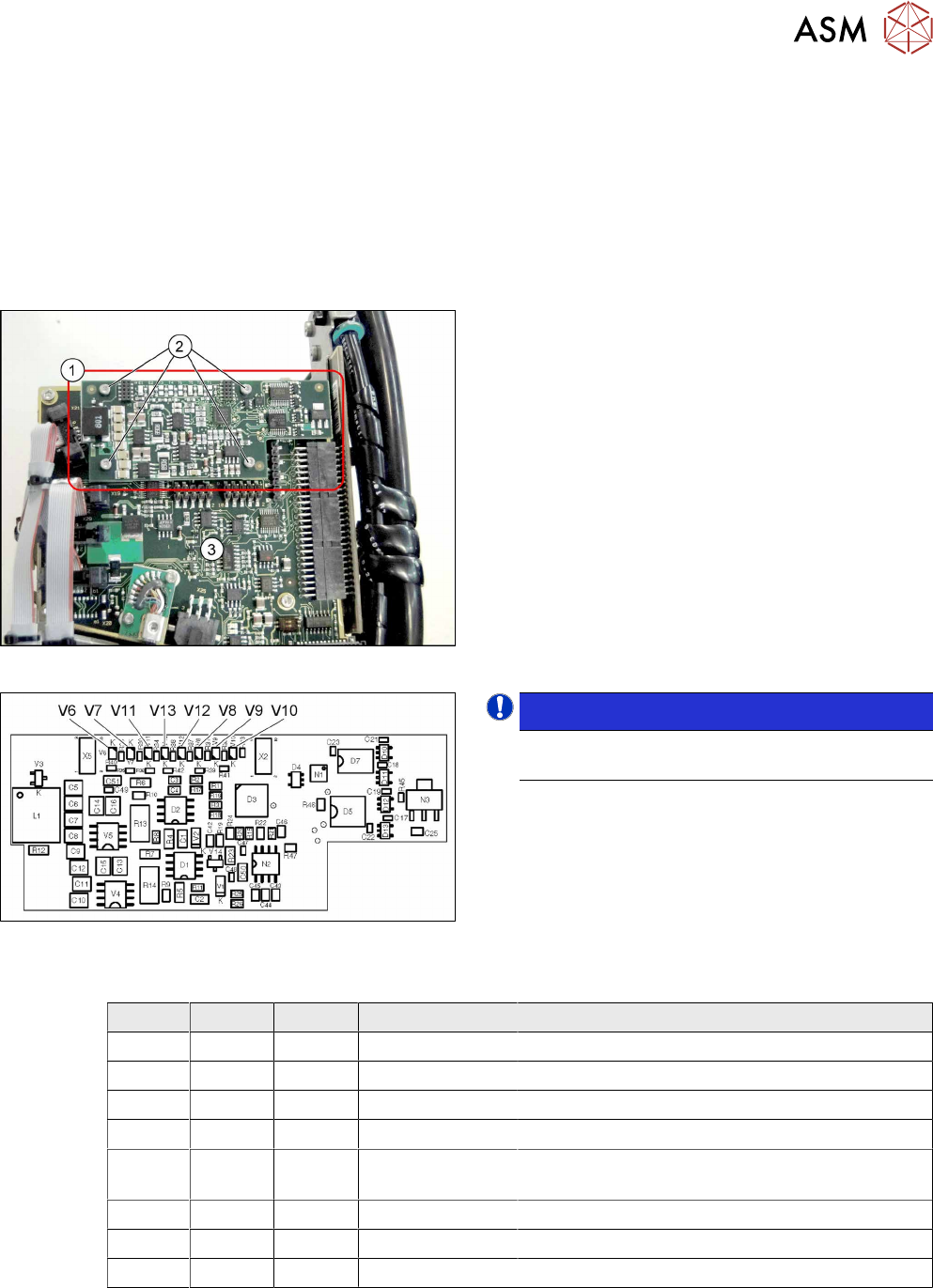
Fig.179: KE control board ID2
1. KE control board ID2
2. Fastening screws for KE control board ID2
3. Intermediate distributor 2 (ID2)
Fig.180: 03073355-02
NOTICE!
The "KE control board ID2" is only used for CPP
heads from version 05 onwards.
.
LED [03073355-02]
LED Color Status Signal name Description
V6 RD ON D3/BANK2/IO[1] Maximum current exceeded
V7 RD ON D3/BANK1/IO[36] Continuous current too high
V8 GN - FPGA_TEST_2 Not used
V9 GN ON FPGA_TEST_4 KE control switched on
V10 RD ON STATUS_24V_D
P
KE transmitter error switched off
V11 GN - FPGA_TEST_5 Not used
V12 GN - FPGA_TEST_1 Not used
V13 GN - FPGA_TEST_3 Not Used