00197463-03_SM_CPP_Customer_EN.pdf - 第65页
5 Front plate, star, Z axis and smoothed distributor disc 5.6 Replacing the energy transmission for the rotor [03068843‑xx] Service Manual SIPLACE Multistar (CPP / CPP M) 02/2018 65 Installation Fig.97: Pins and connect…
5 Front plate, star, Z axis and smoothed distributor disc
5.6 Replacing the energy transmission for the rotor [03068843‑xx]
64 Service Manual SIPLACE Multistar (CPP / CPP M) 02/2018
Removal (for heads from version 05)
► If required, dismantle the front plate.
5.1 "Replacing the front plate [03061102-xx]" [}35]
► Remove the star.
5.2 "Removing and fitting the star (only for heads from FS05 upwards)" [}43]
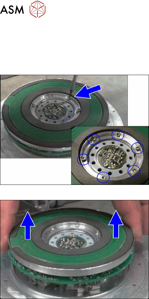
Fig.95: Fastening screws for "energy transmission for rotor"
► Remove the six screws fastening the "energy
transmission for the rotor".
Fig.96: Removing the "energy transmission for the rotor"
► Remove the "energy transmission for the rotor".
5 Front plate, star, Z axis and smoothed distributor disc
5.6 Replacing the energy transmission for the rotor [03068843‑xx]
Service Manual SIPLACE Multistar (CPP / CPP M) 02/2018 65
Installation
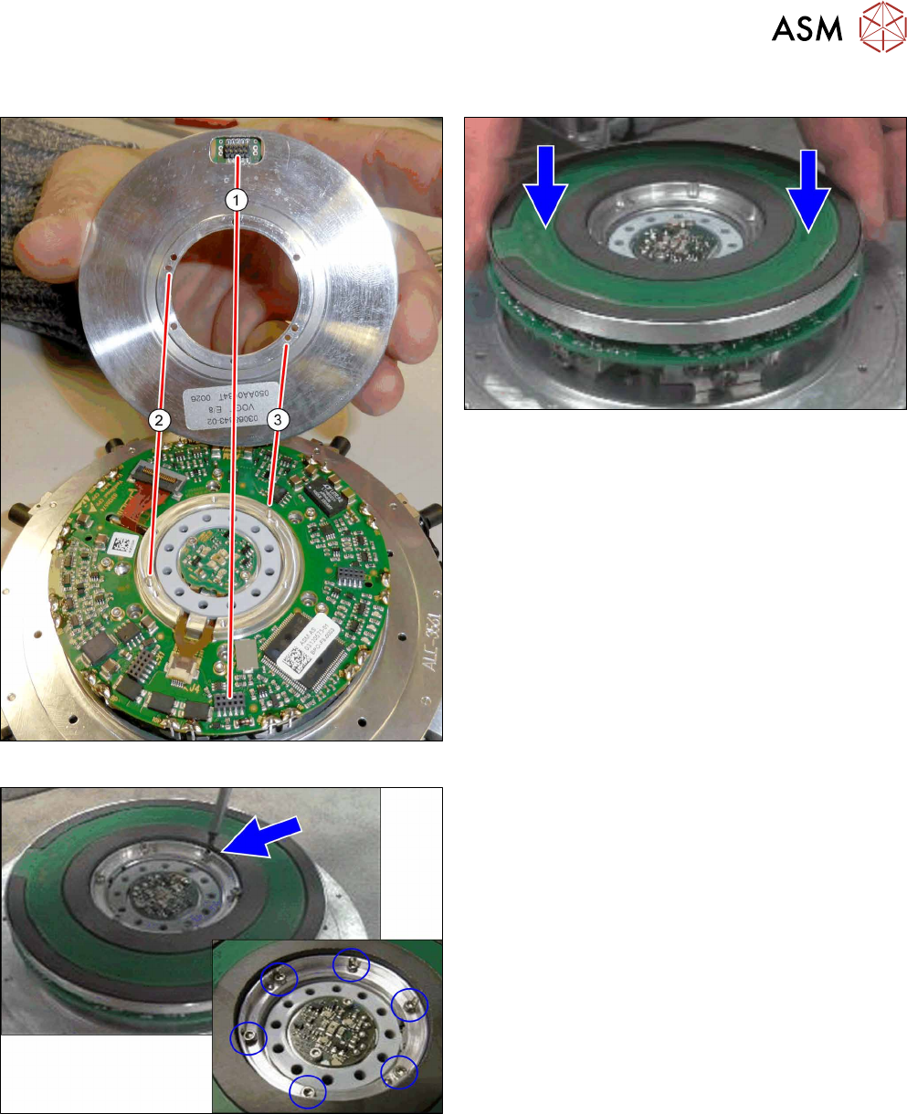
Fig.97: Pins and connectors
Fig.98: Fitting the energy transmission for rotor
► Place the "energy transmission for rotor" onto the
valve terminal.
Make sure that the connector(1) and the pins
at(2) and(3) are correctly positioned.
Fig.99: Fastening the "energy transmission for the rotor"
► Fasten the "energy transmission for rotor" with
six screws.
Tighten the screws crosswise with a torque of
0.10Nm.
► Follow the removal instructions in reverse order for further installation.
Also observe the installation instructions in the following sections:
5.2 "Removing and fitting the star (only for heads from FS05 upwards)" [}43]
5.1 "Replacing the front plate [03061102-xx]" [}35]
5 Front plate, star, Z axis and smoothed distributor disc
5.7 Replacing the energy transmission for the stator [03068842‑xx] (only for heads fromFS05)
66 Service Manual SIPLACE Multistar (CPP / CPP M) 02/2018
5.7 Replacing the energy transmission for the stator
[03068842‑xx] (only for heads fromFS05)
Parts, equipment and tools
●
Energy transmission for rotor assembly CPP [03068843‑xx] (without connection cable)
Overview
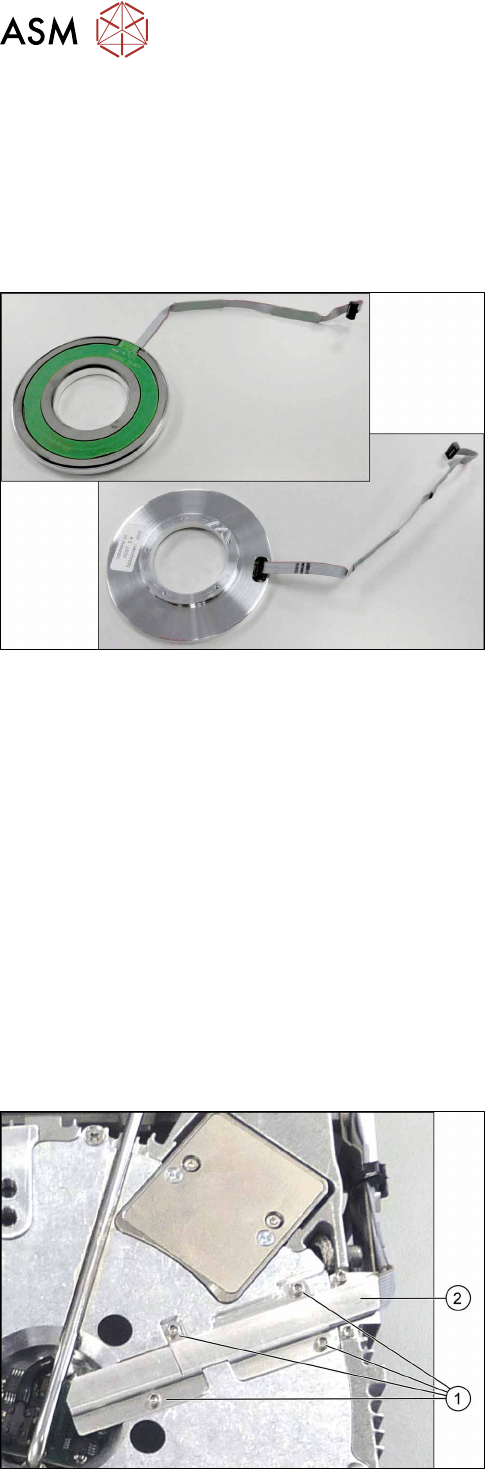
Fig.100: Energy transmission for stator and connection cable
(front and back)
The "energy transmission for the rotor" is located be-
hind the star in the CPP head.
Preparation
► Remove the head from the machine. For details about removing and fitting the placement
head, refer to the service manual for your machine.
fit the head on the head mount [03056231‑xx].
► Make sure that the component sensor protective cap is fitted.
1.1.3 "Protecting the component sensor" [}8]
Removal (for heads from version 05)
► If required, dismantle the front plate.
5.1 "Replacing the front plate [03061102-xx]" [}35]
► Remove the star.
5.2 "Removing and fitting the star (only for heads from FS05 upwards)" [}43]
► Remove the smoothed distributor disc.
5.3 "Replacing the smoothed distributor disc [03055431-xx]" [}47]
Fig.101: Cover
► Turn the head over.
► Remove the four screws (1) fastening the cover
(2) and remove the cover.