00197463-03_SM_CPP_Customer_EN.pdf - 第51页
5 Front plate, star, Z axis and smoothed distributor disc 5.4 Removing the valve terminal (only for heads from FS05 upwards) Service Manual SIPLACE Multistar (CPP / CPP M) 02/2018 51 Installation Fig.72: Checking the se…
5 Front plate, star, Z axis and smoothed distributor disc
5.4 Removing the valve terminal (only for heads from FS05 upwards)
50 Service Manual SIPLACE Multistar (CPP / CPP M) 02/2018
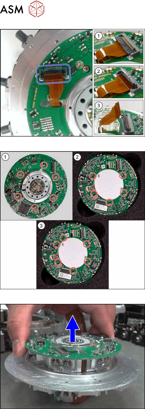
Fig.69: Flexprint cable
1. Connector closed
2. Connector open
3. Flexprint removed
► Open the connector and remove the Flexprint
cable.
Fig.70: Screws fastening the valve terminal
► Remove the screws fastening the valve terminal:
1. The old valve terminal [03082217‑xx] is fixed with
six screws to the heads up to and including
FS04.
2. The new valve terminal [03115167‑xx] is fixed
with five screws to the heads up to number [KL-
J5-0162] .
3. The new valve terminal [03115167‑xx] is fixed
with six screws to heads from number [KL-
J5-0162].
Fig.71: Removing the valve terminal
► Lift the valve terminal off the star carrier.
5 Front plate, star, Z axis and smoothed distributor disc
5.4 Removing the valve terminal (only for heads from FS05 upwards)
Service Manual SIPLACE Multistar (CPP / CPP M) 02/2018 51
Installation
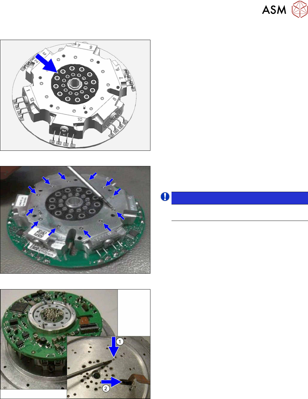
Fig.72: Checking the seal
► Check the position of the seal.
Fig.73: Checking the ball bearings
► Check the ball bearings.
These ball bearings may not protrude above the
surface.
NOTICE!
If the ball bearings are defective, you will
need to replace the valve terminal.
.
Fig.74: Inserting the valve terminal
► Place the valve terminal on the star carrier.
Pay attention to the correct position of the pins
and to the position of the Flexprint cable.
5 Front plate, star, Z axis and smoothed distributor disc
5.4 Removing the valve terminal (only for heads from FS05 upwards)
52 Service Manual SIPLACE Multistar (CPP / CPP M) 02/2018
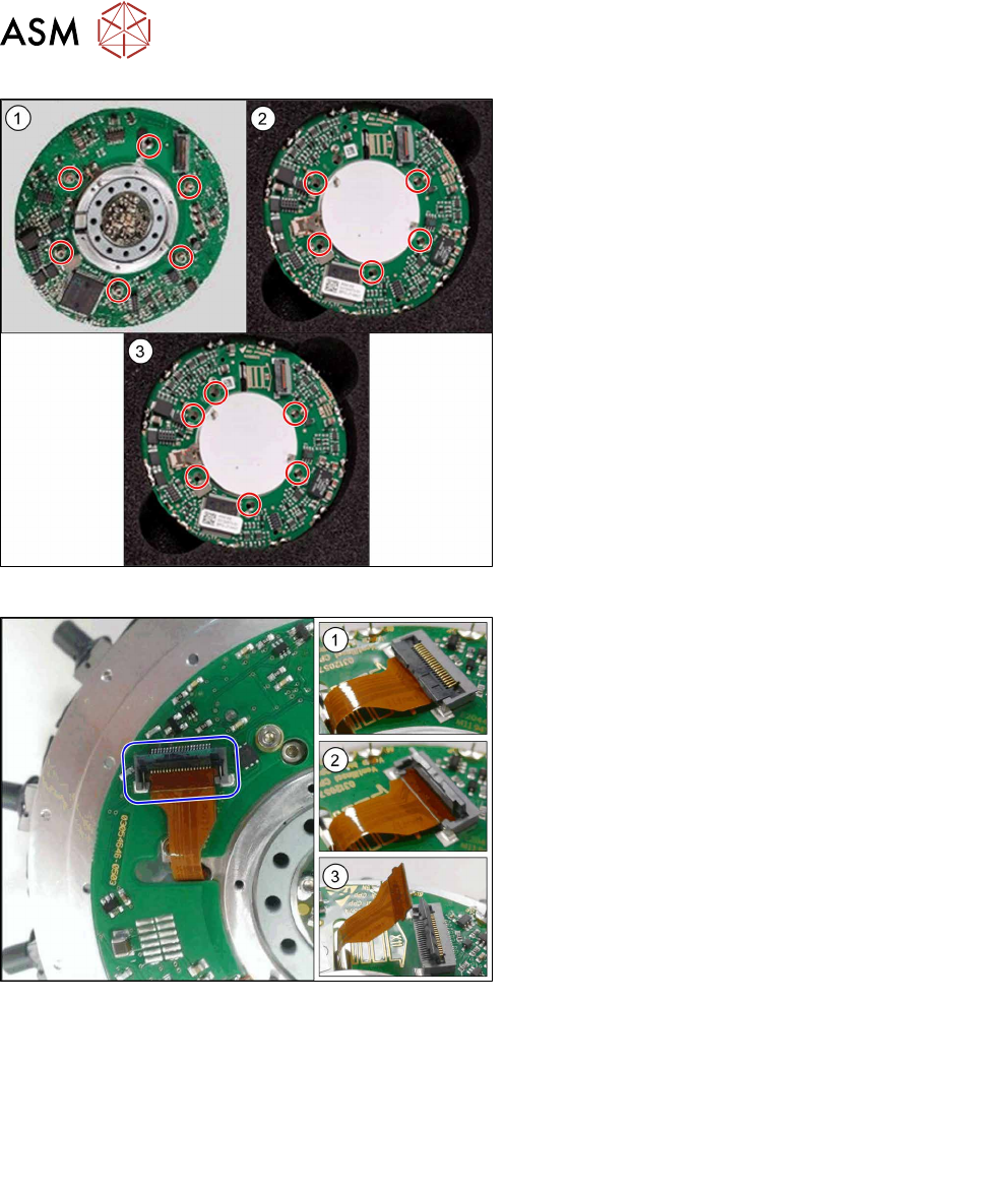
Fig.75: Fastening the valve terminal
1. The old valve terminal [03082217‑xx] is fixed with
six screws to the heads up to and including
FS04.
2. The new valve terminal [03115167‑xx] is fixed
with five screws to the heads up to number [KL-
J5-0162] .
3. The new valve terminal [03115167‑xx] is fixed
with six screws to heads from number [KL-
J5-0162].
► Fasten the valve terminal with the screws
provided.
Tighten the screws crosswise with a torque of
0.17 +/- 0.03Nm.
Fig.76: Flexprint cable
1. Connector closed
2. Connector open
3. Flexprint removed
► Insert the Flexprint cable as far as the stop into
the connector and lock the connector.
► Follow the removal instructions in reverse order for further installation.
Also observe the installation instructions in the following sections:
5.6 "Replacing the energy transmission for the rotor [03068843‑xx]" [}63]
5.2 "Removing and fitting the star (only for heads from FS05 upwards)" [}43]
5.1 "Replacing the front plate [03061102-xx]" [}35]
► Observe in particular the torques specified!