00197463-03_SM_CPP_Customer_EN.pdf - 第42页
5 Front plate, star, Z axis and smoothed distributor disc 5.1 Replacing the front plate [03061102-xx] 42 Service Manual SIPLACE Multistar (CPP / CPP M) 02/2018 Fig.52: Connecting the air hoses ► Attach the air hoses (1…
5 Front plate, star, Z axis and smoothed distributor disc
5.1 Replacing the front plate [03061102-xx]
Service Manual SIPLACE Multistar (CPP / CPP M) 02/2018 41
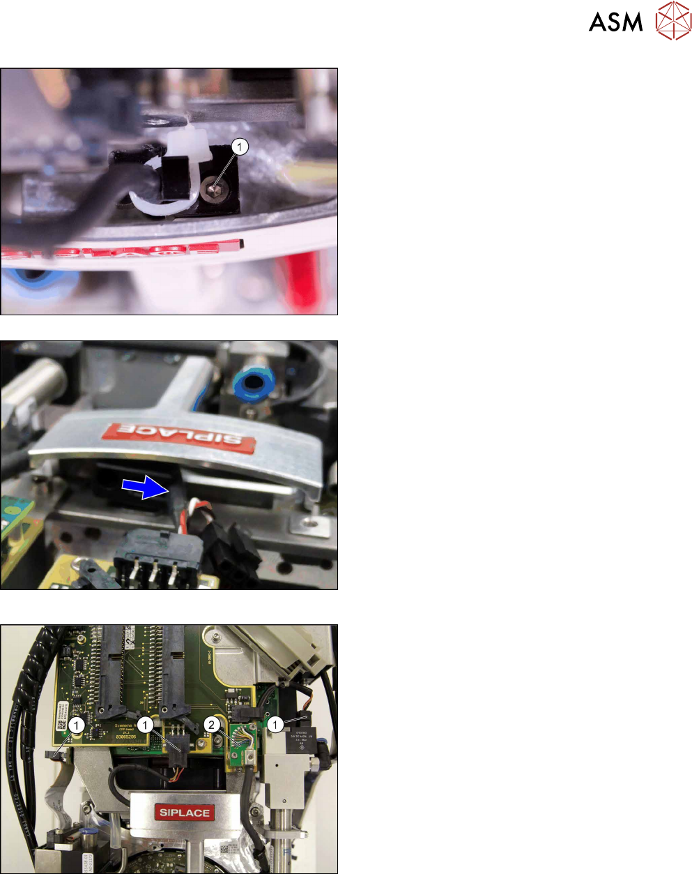
Fig.49: Version with screw
Fig.50: Version without screw
There are two version of fastening the cables to
the handle. Select the appropriate version:
► Version with screw: Replace the cable tie and
fasten the cable with the screw (1).
► Version without screw: Press the cable into the
clamp.
Fig.51: Plugging in the connector
► Plug in the connector(1).
► Plug in the connector (2) and fix the connector
into place with the two fastening screws.
5 Front plate, star, Z axis and smoothed distributor disc
5.1 Replacing the front plate [03061102-xx]
42 Service Manual SIPLACE Multistar (CPP / CPP M) 02/2018
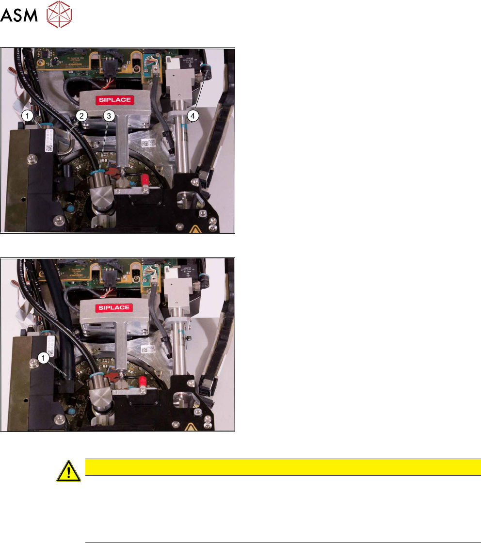
Fig.52: Connecting the air hoses
► Attach the air hoses(1) to(4) for the return unit,
the screwed joint and the pressure control valve.
Pay attention to the correct installation position of
all air hoses.
Fig.53: Connecting the hose to the PRV
► Fit the air hose (1) to the pressure control valve.
CAUTION
Other installation instructions
► After performing installation, start the station software and check the zero point correc-
tion value for the Z axis.
► In the event of problems or if the data is not automatically applied, import the zero
point correction data from the head EEPROM into the machine data.
5 Front plate, star, Z axis and smoothed distributor disc
5.2 Removing and fitting the star (only for heads from FS05 upwards)
Service Manual SIPLACE Multistar (CPP / CPP M) 02/2018 43
5.2 Removing and fitting the star (only for heads from FS05
upwards)
Overview
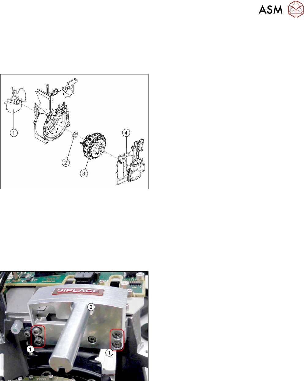
Fig.54: CPP head structure
1. Back plate
2. Smoothed distributor disc
3. Star
4. Front plate
Preparation
► Remove the head from the machine. For details about removing and fitting the placement
head, refer to the service manual for your machine.
fit the head on the head mount [03056231‑xx].
► Make sure that the component sensor protective cap is fitted.
1.1.3 "Protecting the component sensor" [}8]
Removal
Fig.55: Handle
► Remove the four screws(1) fastening the
handle(2) and remove the handle.