00197463-03_SM_CPP_Customer_EN.pdf - 第92页
7 Pressure control valve (PRV) 7.5 Exhaust air hose for CPP [03077294‑xx] 92 Service Manual SIPLACE Multistar (CPP / CPP M) 02/2018 Fig.153: Fastening the board Fasten the board with five self-tapping screws (1) to (5…
7 Pressure control valve (PRV)
7.4 Replacing small parts on the PRV
Service Manual SIPLACE Multistar (CPP / CPP M) 02/2018 91
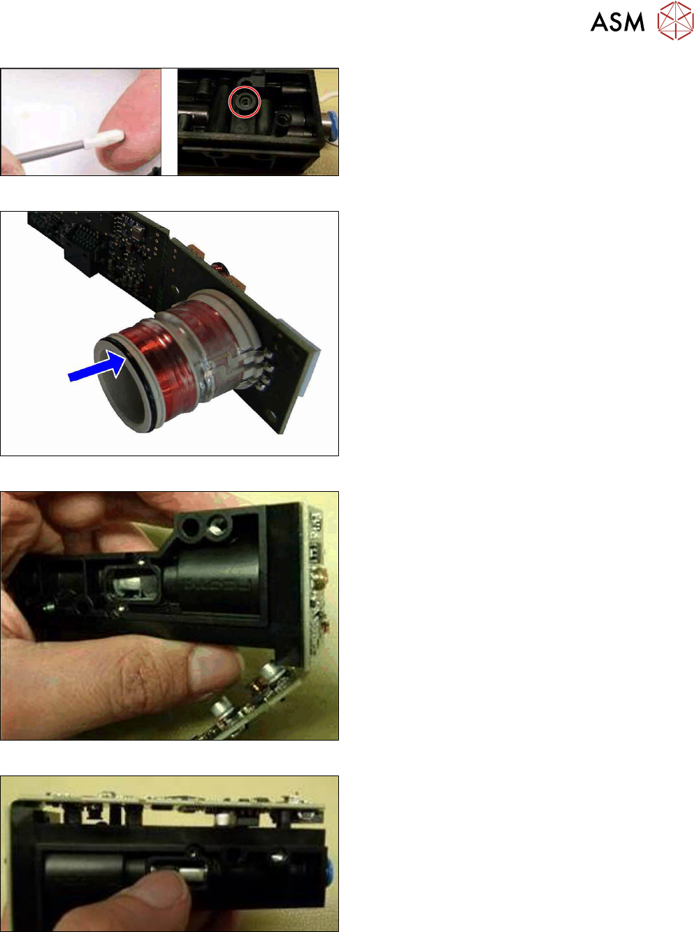
Fig.149: Inserting the O-ring
► Grease the O-ring all around with a lint-free cot-
ton swab and "Isoflex Topas
5051" [03078517‑xx].
► Now insert the O-ring into the housing.
Fig.150: Greasing the O-ring
► Grease the O-ring slightly with a lint-free cotton
swab and "Isoflex Topas 5051" [03078517‑xx].
Fig.151: Inserting the board
► Push the board and coil into the housing.
Fig.152: Positioning the top part of the board
► Place the top part of the board onto the housing.
7 Pressure control valve (PRV)
7.5 Exhaust air hose for CPP [03077294‑xx]
92 Service Manual SIPLACE Multistar (CPP / CPP M) 02/2018
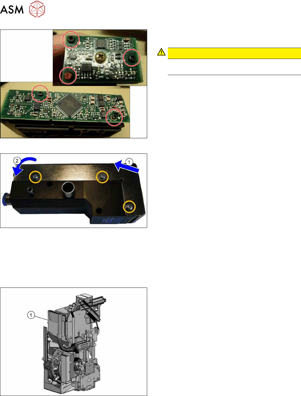
Fig.153: Fastening the board
Fasten the board with five self-tapping screws(1)
to(5). To do so, proceed as follows:
CAUTION!
If possible, always use new screws of type PT-
WN1442-2.5X8-PT10.
.
► First check the thread by turning the screws
slightly to the left.
► Then fasten the screws with a torque of 0.2Nm.
Fig.154: Fitting the cover
► (1) Fit the cover at the top and (2) close it over
the printed circuit board.
► Fasten the cover with three screws. To do so,
proceed as follows:
– First check the thread by turning the screws
slightly to the left.
– Then fasten the screws with a torque of
0.20Nm.
► Follow the removal instructions in reverse order for further installation.
Also observe the installation instructions in the following section:
7.1 "Replacing the PRV [03072785‑xx]" [}79]
7.5 Exhaust air hose for CPP [03077294‑xx]
Fig.155: Exhaust air hose for CPP [03077294‑xx]
► Check the length of the exhaust air hose(1):
– Exhaust air hose CPP [03077294‑xx]:
318mm
See also
2 3 "Usability package" [}25]
8 Screwed joint, silencer and holding circuit
8.1 Overview of screwed joint, holding circuit and seals
Service Manual SIPLACE Multistar (CPP / CPP M) 02/2018 93
8 Screwed joint, silencer and holding circuit
8.1 Overview of screwed joint, holding circuit and seals
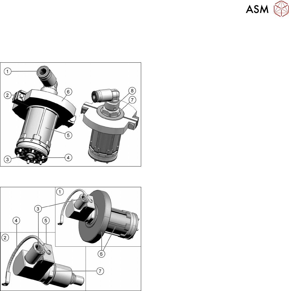
Fig.156: Screwed joint and holding circuit with two-part silencer
– up to version 04
1. Compressed air inlet 4.5bar on the screwed joint
2. Retaining clips for silencer
3. Inner holes:
Venturi nozzle inlet (compressed air)
Outer holes: vacuum to the DP segments.
4. Fixture of holding circuit to star carrier
(sixscrews)
5. Holding circuit housing (plastic)
6. Two-part silencer
7. Fixture nut for the screwed joint
8. Screwed joint
Fig.157: Screwed joint and holding circuit with one-part silencer
– from version 05 (retroactively compatible)
1. Screwed joint and holding circuit housing with
one-part silencer
2. Individual screwed joint
3. Compressed air inlet 4.5bar on the screwed joint
4. Ground connection of screwed joint to the front
plate
5. Collector ring cover
6. Holding circuit housing (plastic) with one-part si-
lencer
7. Fixture nut for the screwed joint