00197463-03_SM_CPP_Customer_EN.pdf - 第105页
9 Intermediate distributor and vacuum sensor 9.1 Replacing the KE Control Board ZV2 [03073355-xx] Service Manual SIPLACE Multistar (CPP / CPP M) 02/2018 105 9 Intermediate distributor and vacuum sensor 9.1 Replacing the …
8 Screwed joint, silencer and holding circuit
8.4 Replacing the holding circuit
104 Service Manual SIPLACE Multistar (CPP / CPP M) 02/2018
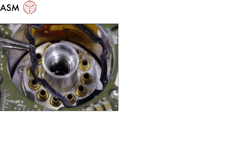
Fig.178: Inserting the seal
► Put on the top seal.
► Follow the removal instructions in reverse order for further installation.
Also observe the installation instructions in the following sections:
8.3.3 "Replacing the silencer" [}97]
8.2 "Replacing the screwed joint" [}94]
5.1 "Replacing the front plate [03061102-xx]" [}35]
► Observe in particular the torques specified!
9 Intermediate distributor and vacuum sensor
9.1 Replacing the KE Control Board ZV2 [03073355-xx]
Service Manual SIPLACE Multistar (CPP / CPP M) 02/2018 105
9 Intermediate distributor and vacuum sensor
9.1 Replacing the KE Control Board ZV2 [03073355-xx]
Parts, equipment and tools
●
KE control board ID2 [03073355-xx]
Overview
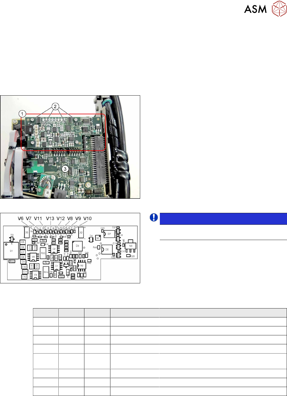
Fig.179: KE control board ID2
1. KE control board ID2
2. Fastening screws for KE control board ID2
3. Intermediate distributor 2 (ID2)
Fig.180: 03073355-02
NOTICE!
The "KE control board ID2" is only used for CPP
heads from version 05 onwards.
.
LED [03073355-02]
LED Color Status Signal name Description
V6 RD ON D3/BANK2/IO[1] Maximum current exceeded
V7 RD ON D3/BANK1/IO[36] Continuous current too high
V8 GN - FPGA_TEST_2 Not used
V9 GN ON FPGA_TEST_4 KE control switched on
V10 RD ON STATUS_24V_D
P
KE transmitter error switched off
V11 GN - FPGA_TEST_5 Not used
V12 GN - FPGA_TEST_1 Not used
V13 GN - FPGA_TEST_3 Not Used
9 Intermediate distributor and vacuum sensor
9.1 Replacing the KE Control Board ZV2 [03073355-xx]
106 Service Manual SIPLACE Multistar (CPP / CPP M) 02/2018
Preparation
► Remove the head from the machine. For details about removing and fitting the placement
head, refer to the service manual for your machine.
fit the head on the head mount [03056231‑xx].
► Make sure that the component sensor protective cap is fitted.
1.1.3 "Protecting the component sensor" [}8]
Removal
► Remove the screwsfastening the board.
► Carefully pull the board off the ID2. Pay particular attention to the connectors on the underside
of the board.
Installation
► Follow the removal instructions in reverse order for installation. Also observe the following in-
structions:
CAUTION
Installation instructions
► Make sure that you do not damage the connectors on the underside of the board.