00197463-03_SM_CPP_Customer_EN.pdf - 第39页
5 Front plate, star, Z axis and smoothed distributor disc 5.1 Replacing the front plate [03061102-xx] Service Manual SIPLACE Multistar (CPP / CPP M) 02/2018 39 Installation ► Remove the pressure control valve from the ol…
5 Front plate, star, Z axis and smoothed distributor disc
5.1 Replacing the front plate [03061102-xx]
38 Service Manual SIPLACE Multistar (CPP / CPP M) 02/2018
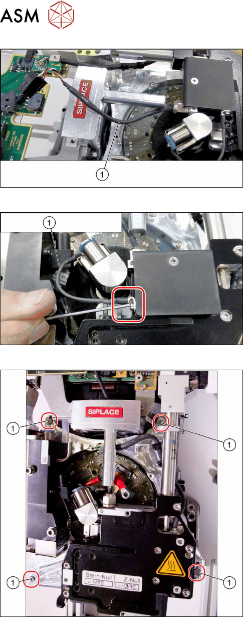
Fig.41: Removing the cable
► Carefully release the cable(1) from its holder.
Fig.42: Unscrewing the ground connection for the screwed joint
► Remove the screw fastening the ground connec-
tion(1).
Fig.43: Removing the front plate
► Remove the fourscrews(1) fastening the front
plate and remove the front plate.
5 Front plate, star, Z axis and smoothed distributor disc
5.1 Replacing the front plate [03061102-xx]
Service Manual SIPLACE Multistar (CPP / CPP M) 02/2018 39
Installation
► Remove the pressure control valve from the old and fit in the new front plate.
7.1 "Replacing the PRV [03072785‑xx]" [}79]
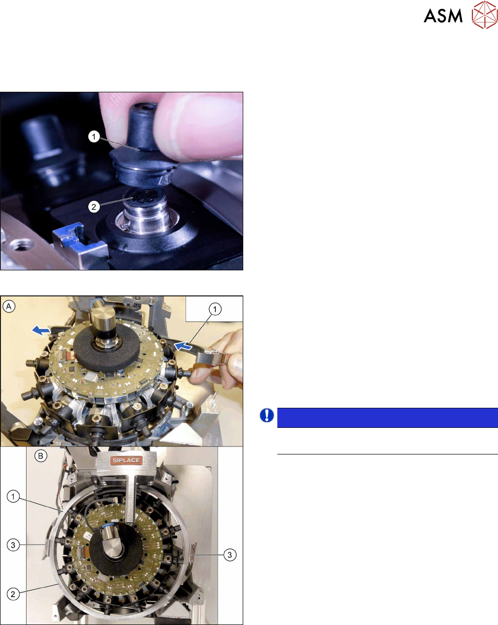
Fig.44: Fitting the calibration nozzles
► Attach a calibration nozzle (type 2057)(1) on
each DP drive(2).
Fig.45: Inserting the DP clamping ring
Threading the driver bearings at the DP drives into the
raceway:
► Thread one half of the DP clamping ring(1) diag-
onally under the star and through.
► Thread the other half of the DP clamping ring(2)
in at the other end of the star.
► Spread both parts of the DP clamping ring(1+2)
over the type 2057 nozzles.
NOTICE!
Make sure that the two turnbuckles(3) are at
the side of the head.
.
► Close the two turnbuckles one all nozzles have
been properly threaded in.
5 Front plate, star, Z axis and smoothed distributor disc
5.1 Replacing the front plate [03061102-xx]
40 Service Manual SIPLACE Multistar (CPP / CPP M) 02/2018
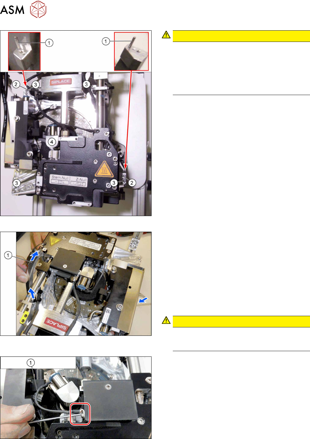
Fig.46: Fitting the front plate
CAUTION!
Do not press!
Do not apply pressure to the front plate. As soon
as the driver bearing is correctly positioned, the
front plate should slide without effort onto the
centering pins (watch the screwed joint, see be-
low). The driver bearing could be damaged oth-
erwise.
.
► First place the front plate loosely on the head.
The two holes(2) in the front plate must be posi-
tioned over the two centering pins(1) for the
head.
► Now thread in the front plate. Observe the follow-
ing points:
– First turn the screwed joint to the left and
thread the front plate in as far as possible.
Then turn the screwed joint upwards to the
handle and fully insert the front plate.
– Carefully move the DP clamping ring back
and forth, until the front plate drops down-
wards.
► Tighten the four screws(2) fastening the front
plate cross-wise and evenly with a torque of
0.85Nm.
Fig.47: Removing the DP clamping ring
► Open the turnbuckles for the DP clamping ring.
► Carefully unthread the two parts of the DP clamp-
ing ring from the head, one after the other. To do
so, proceed as follows:
– Take hold of the DP clamping ring by its turn-
buckle.
– Turn the DP clamping ring by about 60 to 70
degrees (until almost vertical to the star).
– Carefully pull the DP clamping ring out of the
head.
CAUTION!
Always pull from the side with the turn-
buckle. Do not pull the turnbuckle through
the head.
.
Fig.48: Fastening the ground connection for the screwed joint
► Fasten the ground connection(1) to the screwed
joint.