00197463-03_SM_CPP_Customer_EN.pdf - 第71页
6 DP drives 6.1 Replacing the DP drives Service Manual SIPLACE Multistar (CPP / CPP M) 02/2018 71 6 DP drives 6.1 Replacing the DP drives Parts, equipment and tools ● Select the correct DP drive: – CPP : DP drive assembl…

5 Front plate, star, Z axis and smoothed distributor disc
5.7 Replacing the energy transmission for the stator [03068842‑xx] (only for heads fromFS05)
70 Service Manual SIPLACE Multistar (CPP / CPP M) 02/2018
6 DP drives
6.1 Replacing the DP drives
Service Manual SIPLACE Multistar (CPP / CPP M) 02/2018 71
6 DP drives
6.1 Replacing the DP drives
Parts, equipment and tools
●
Select the correct DP drive:
– CPP: DP drive assembly (incl. 3 screws, without linear guide) [03050314-xx]
– CPP M: DP drive assembly – CPPM [03153724‑xx]
Overview
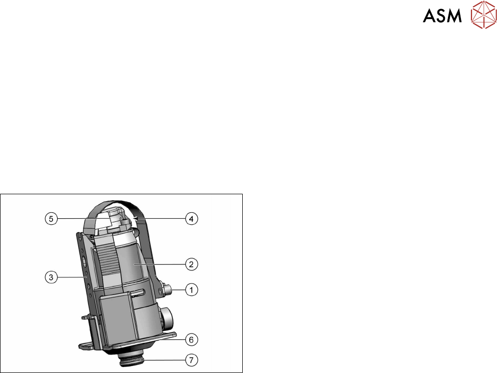
Fig.109: DP drive
1. The connector is connected and screwed to the
SCS control unit.
2. Motor
3. Fixture surface for screwing the linear guidance
into place
4. Vacuum connection.
5. Measuring system
Resolution: 278digitsperdegree or
100,000digitsperrevolution
6. Protective cap
7. Nozzle interface
Preparation
► Remove the head from the machine. For details about removing and fitting the placement
head, refer to the service manual for your machine.
fit the head on the head mount [03056231‑xx].
► Make sure that the component sensor protective cap is fitted.
1.1.3 "Protecting the component sensor" [}8]
6 DP drives
6.1 Replacing the DP drives
72 Service Manual SIPLACE Multistar (CPP / CPP M) 02/2018
Removal
► If required, dismantle the front plate.
5.1 "Replacing the front plate [03061102-xx]" [}35]
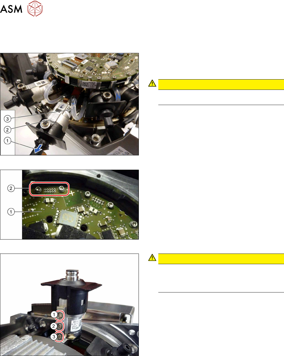
Fig.110: Pulling out the DP drive
► Pull the nozzle (1) off the DP drive.
► Pull the DP drive (2), together with the jaws, out
of the head.
CAUTION!
Do not pull on the black cover. This might break
if you do.
.
► Remove the hose(3) on both sides.
Fig.111: Connector fastening screws
► Remove the two screws(2) fastening the Flex-
print cable to the SCS(1).
► Disconnect the cable.
Fig.112: DP drive fastening screws
CAUTION!
When loosening the screws, carefully press
against the DP drive. This prevents excess force
being applied to the linear guide, which could
otherwise be damaged.
.
► First remove the screws (1) and (2).
► Then remove this screw(3). Use the special ball-
head Allen key.
► Remove the DP drive.