00197463-03_SM_CPP_Customer_EN.pdf - 第66页
5 Front plate, star, Z axis and smoothed distributor disc 5.7 Replacing the energy transmission for the stator [03068842‑xx] (only for heads fromFS05) 66 Service Manual SIPLACE Multistar (CPP / CPP M) 02/2018 5.7 Replac…
5 Front plate, star, Z axis and smoothed distributor disc
5.6 Replacing the energy transmission for the rotor [03068843‑xx]
Service Manual SIPLACE Multistar (CPP / CPP M) 02/2018 65
Installation
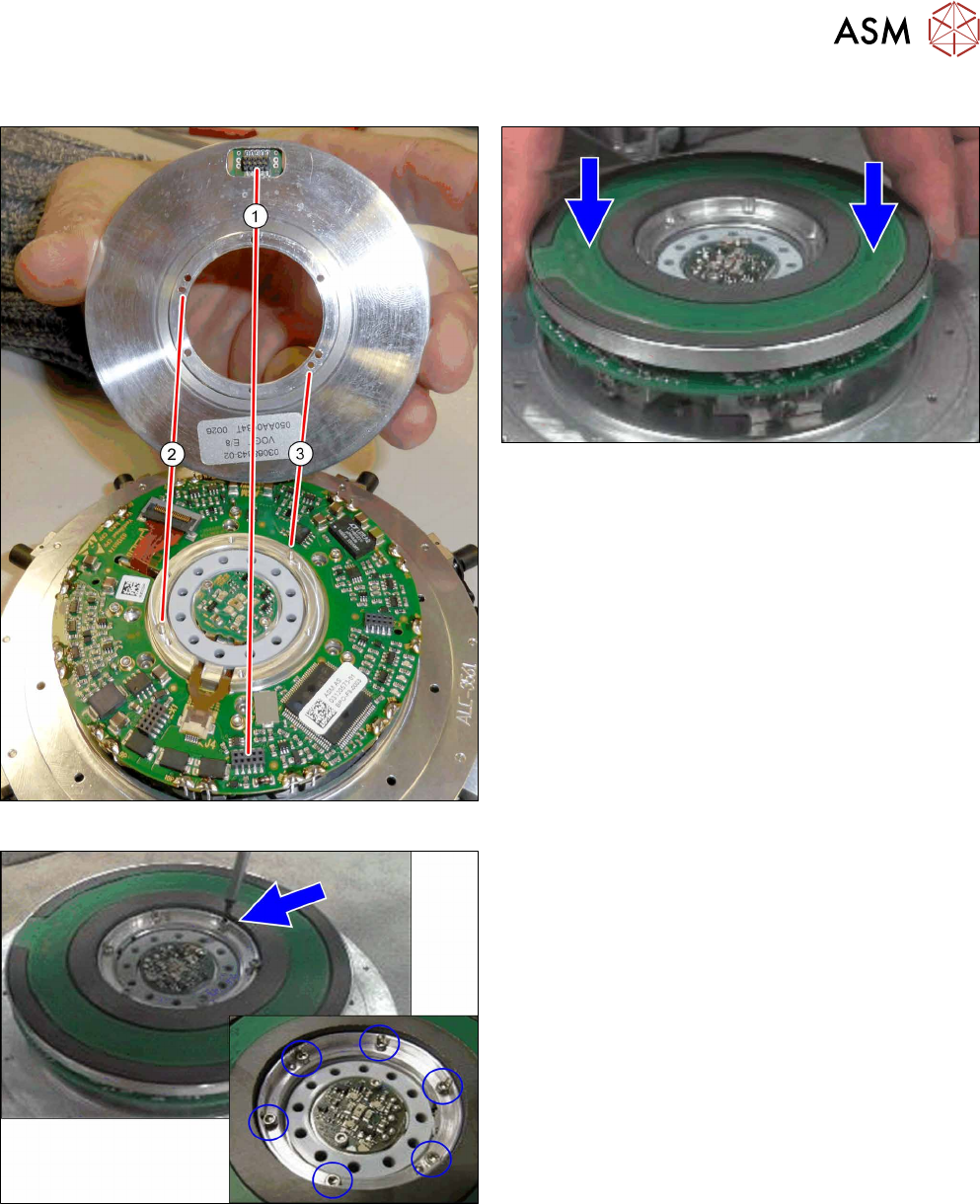
Fig.97: Pins and connectors
Fig.98: Fitting the energy transmission for rotor
► Place the "energy transmission for rotor" onto the
valve terminal.
Make sure that the connector(1) and the pins
at(2) and(3) are correctly positioned.
Fig.99: Fastening the "energy transmission for the rotor"
► Fasten the "energy transmission for rotor" with
six screws.
Tighten the screws crosswise with a torque of
0.10Nm.
► Follow the removal instructions in reverse order for further installation.
Also observe the installation instructions in the following sections:
5.2 "Removing and fitting the star (only for heads from FS05 upwards)" [}43]
5.1 "Replacing the front plate [03061102-xx]" [}35]
5 Front plate, star, Z axis and smoothed distributor disc
5.7 Replacing the energy transmission for the stator [03068842‑xx] (only for heads fromFS05)
66 Service Manual SIPLACE Multistar (CPP / CPP M) 02/2018
5.7 Replacing the energy transmission for the stator
[03068842‑xx] (only for heads fromFS05)
Parts, equipment and tools
●
Energy transmission for rotor assembly CPP [03068843‑xx] (without connection cable)
Overview
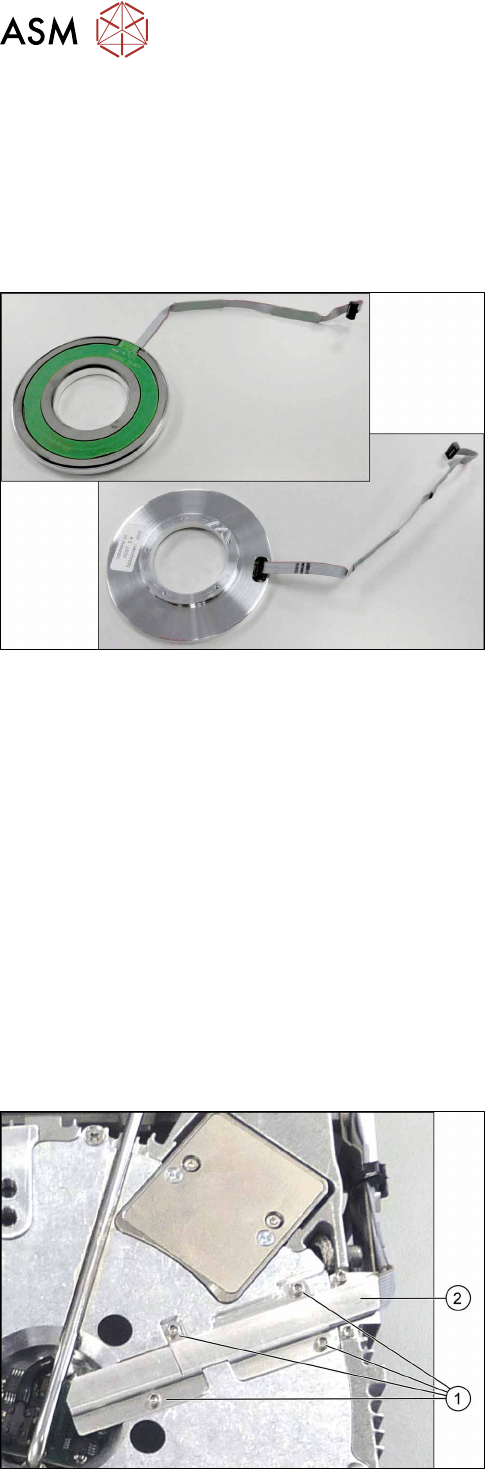
Fig.100: Energy transmission for stator and connection cable
(front and back)
The "energy transmission for the rotor" is located be-
hind the star in the CPP head.
Preparation
► Remove the head from the machine. For details about removing and fitting the placement
head, refer to the service manual for your machine.
fit the head on the head mount [03056231‑xx].
► Make sure that the component sensor protective cap is fitted.
1.1.3 "Protecting the component sensor" [}8]
Removal (for heads from version 05)
► If required, dismantle the front plate.
5.1 "Replacing the front plate [03061102-xx]" [}35]
► Remove the star.
5.2 "Removing and fitting the star (only for heads from FS05 upwards)" [}43]
► Remove the smoothed distributor disc.
5.3 "Replacing the smoothed distributor disc [03055431-xx]" [}47]
Fig.101: Cover
► Turn the head over.
► Remove the four screws (1) fastening the cover
(2) and remove the cover.
5 Front plate, star, Z axis and smoothed distributor disc
5.7 Replacing the energy transmission for the stator [03068842‑xx] (only for heads fromFS05)
Service Manual SIPLACE Multistar (CPP / CPP M) 02/2018 67
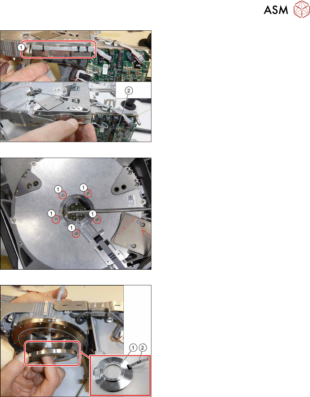
Fig.102: Cables and cable ties
► Remove the cable ties(1).
► Unthread the cable as far as the intermediate dis-
tributor2(2) and then unplug the cable.
You may want to mark the position, to make clear
assignment easier later on.
Fig.103: Fastening screws for energy transmission stator
► Remove the five screws(1) fastening the "energy
transmission stator".
While doing so, hold the "energy transmission
stator" firmly so that these do not fall down (see
also the next step).
Fig.104: Removing the energy transmission stator
► Carefully remove the "energy transmission for
stator"(1) from the head.
Unplug the cable(2) for the "energy transmission
for stator".