00197463-03_SM_CPP_Customer_EN.pdf - 第19页
2 Overview of the Modules 2.1 CPP Head Service Manual SIPLACE Multistar (CPP / CPP M) 02/2018 19 2.1.3 Retract unit Fig.7: Return unit 1. Pneumatic cylinder 2. Solenoid valve 3. Compressed air connection 4. Z axis drive…
2 Overview of the Modules
2.1 CPP Head
18 Service Manual SIPLACE Multistar (CPP / CPP M) 02/2018
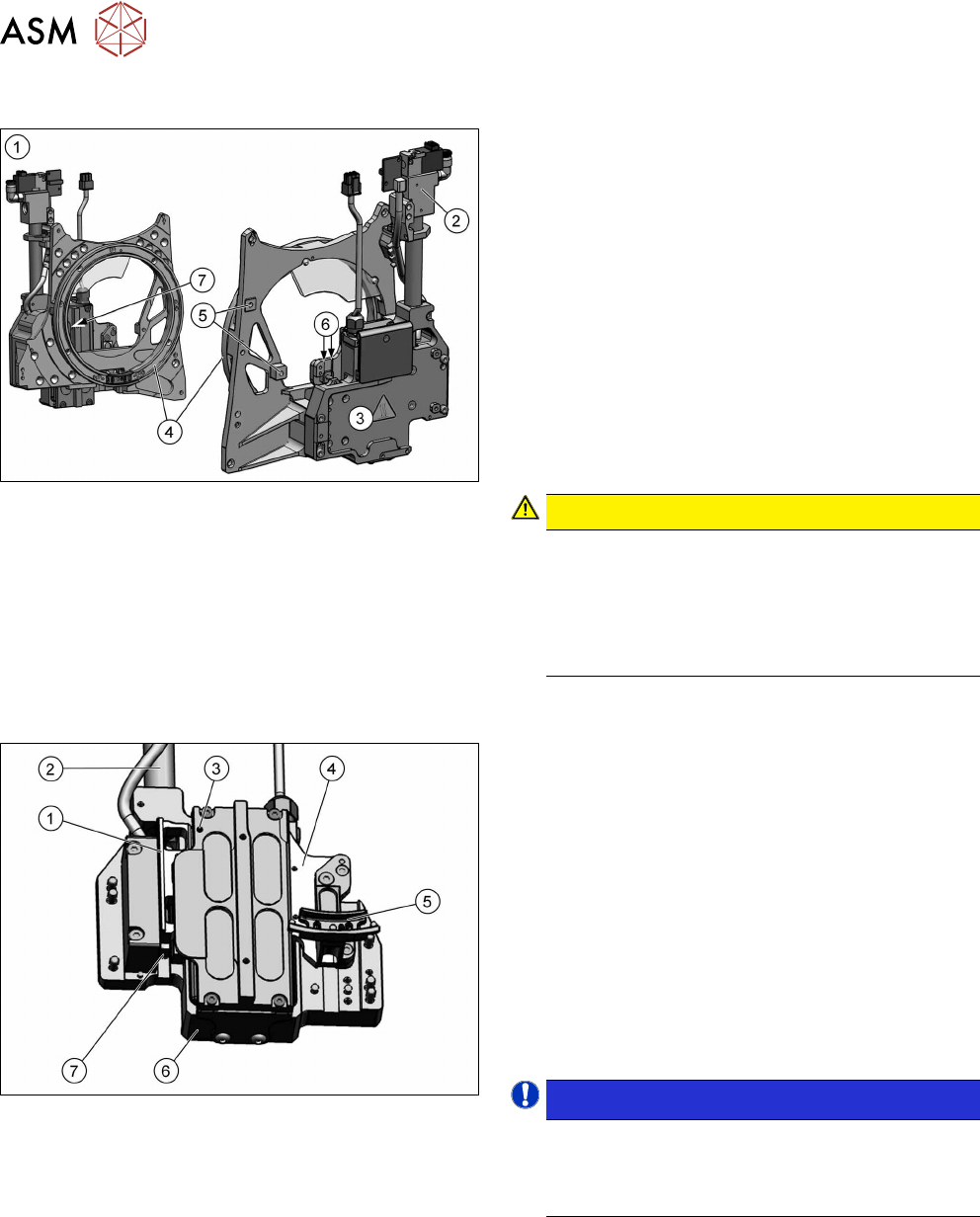
2.1.1 Front plate
Fig.5: Front plate
1. Front plate
2. Return cylinder
3. Z axis with jaws and measuring system
4. Raceway
5. Fixture for pressure control valve
6. Lubrication linear guidance Z axis
7. Lubrication service hole support roller – Z axis
(not present for all head versions. See 2.1.2 "Z
Axis" [}18])
The front plate of the CPP head is fixed to the head
housing with four screws and can be removed as a
whole unit for service purposes.
CAUTION!
Do not dismantle any attachments
Do not dismantle (remove) any parts attached to
the front plate, unless it is explicitly permitted. All
attachments are coordinated with one another
and require special settings (except the pressure
control valve).
.
2.1.2 Z Axis
Fig.6: Z-axis
1. Incremental measurement system, resolution
0.5µm
2. Return unit
3. Service hole for lubricating the Z axis support
roller
4. Secondary part with magnets
The secondary part is fitted to the Z axis.
5. Jaws
The jaws are fitted to the linear guidance of the
Z axis.
6. Linear motor, primary part
7. Actuator on the return unit
NOTICE!
If there is no yellow dot at the position (3) and no
service hole for oiling the support roller then
there is no need to oil it. See also the preventive
maintenance manual of your machine.
.
2 Overview of the Modules
2.1 CPP Head
Service Manual SIPLACE Multistar (CPP / CPP M) 02/2018 19
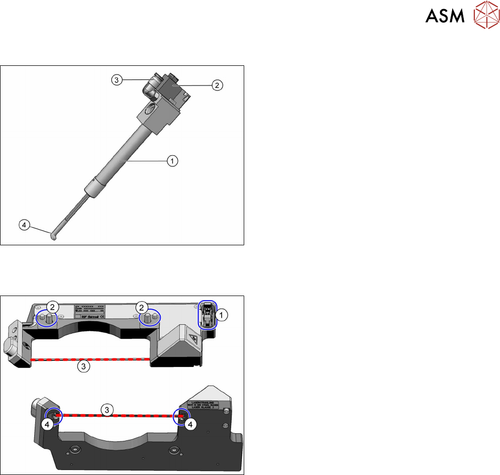
2.1.3 Retract unit
Fig.7: Return unit
1. Pneumatic cylinder
2. Solenoid valve
3. Compressed air connection
4. Z axis driver
The return unit is fixed to the Z axis. This return unit
keeps the Z axis in the safe, upper position during
zero current. This ensures that the placement head is
not damaged when the machine is switched off or in
the event of a power cut.
The return unit is not a spare part and can only be
replaced together with the complete front plate of the
head.
2.1.4 CO sensor
Fig.8: Component sensor (example of C&P20P shown)
1. Power/data supply connector
2. Fixture to head housing
(2x centering pins, 2x screws)
3. Laser beam
4. Transmitter and receiver unit with protected
prisms
2 Overview of the Modules
2.1 CPP Head
20 Service Manual SIPLACE Multistar (CPP / CPP M) 02/2018
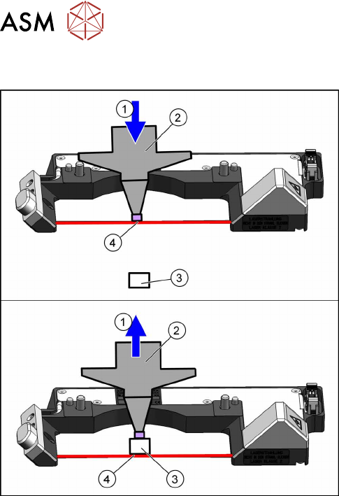
2.1.4.1 Component Sensor Functions
Fig.9: Component sensor function (example of C&P20P used)
1. Downwards (top diagram) or upwards (bottom
diagram) movement
2. Nozzle
3. Component
4. Reading out the Z position, if the laser beam is
interrupted (top diagram) or has been released
again (bottom diagram).
The component sensor signal is directly linked to the
axis controller (measurement system) of the Z axis.
This enables you to read out the Z position during up-
wards and downwards movement.
Pickup process:
When the Z axis moves downwards, the nozzle interrupts the laser beam. At this exact moment,
this Z axis position is read out and compared to the reference value, from the height reference run,
or with this segment after placement. This determines whether there is still a component on the
nozzle or not. If the Z axis position indicates that there is a component on the nozzle, the Z axis will
be immediately stopped. An error message will be issued and the component will be rejected and
sent via the repair cycle, as it will not be placed.
When the Z axis moves upwards again, the laser beam is released and the Z position recorded.
Based on the Z position during downwards movement, the system can now determine the pres-
ence and height of a component.
Placement process:
During the placement process, the system checks whether the component is on the nozzle (Z
downwards movement) or whether placement has been performed on the component (Z upwards
movement). As a precaution, these Z positions are compared to those from the pickup procedure.
This ensures maximum pickup and placement reliability.