00197463-03_SM_CPP_Customer_EN.pdf - 第49页
5 Front plate, star, Z axis and smoothed distributor disc 5.4 Removing the valve terminal (only for heads from FS05 upwards) Service Manual SIPLACE Multistar (CPP / CPP M) 02/2018 49 5.4 Removing the valve terminal (only…
5 Front plate, star, Z axis and smoothed distributor disc
5.3 Replacing the smoothed distributor disc [03055431-xx]
48 Service Manual SIPLACE Multistar (CPP / CPP M) 02/2018
Preparation
► Remove the head from the machine. For details about removing and fitting the placement
head, refer to the service manual for your machine.
fit the head on the head mount [03056231‑xx].
► Make sure that the component sensor protective cap is fitted.
1.1.3 "Protecting the component sensor" [}8]
Removal (for heads from version 05)
► If required, dismantle the front plate.
5.1 "Replacing the front plate [03061102-xx]" [}35]
► Remove the star.
5.2 "Removing and fitting the star (only for heads from FS05 upwards)" [}43]
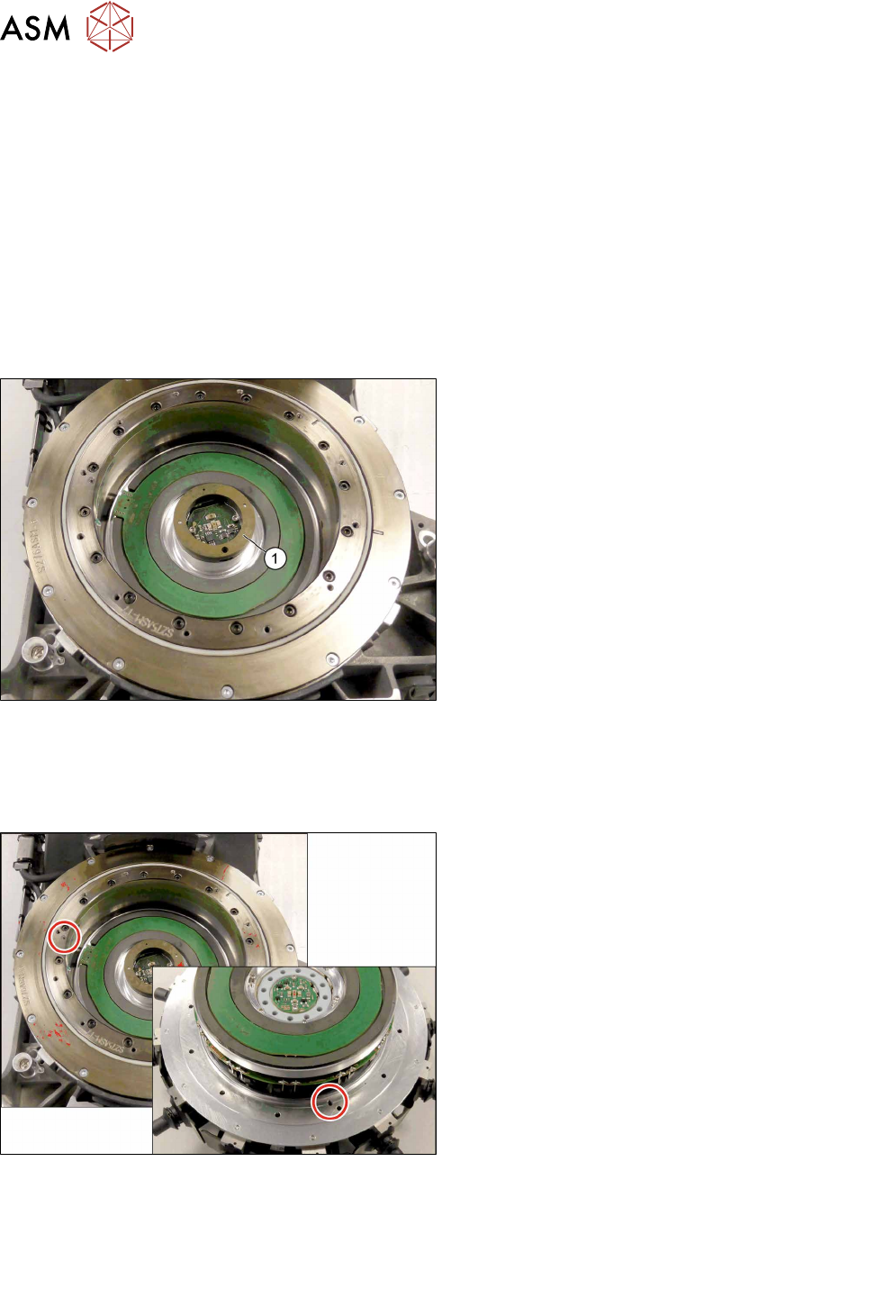
Fig.65: Smoothed distributor disc in the head
► Remove the smoothed distributor disc (1) from
the head. Pay attention to the position of the
smoothed distributor disc to ensure correct re-
assembly.
Installation
► Follow the removal instructions in reverse order for installation. Also observe the following in-
structions:
Fig.66: Pins
► Make sure that the smoothed distributor disc is
fitted correctly between the back plate and the
star (grooves). The pins on the smoothed distrib-
utor disc must point in the direction of the back
plate.
► When inserting the star, make sure that the pin
on the head is inserted into the relevant recess in
the head.
► Follow the removal instructions in reverse order for further installation.
Also observe the installation instructions in the following sections:
5.2 "Removing and fitting the star (only for heads from FS05 upwards)" [}43]
5.1 "Replacing the front plate [03061102-xx]" [}35]
► Observe in particular the torques specified!
5 Front plate, star, Z axis and smoothed distributor disc
5.4 Removing the valve terminal (only for heads from FS05 upwards)
Service Manual SIPLACE Multistar (CPP / CPP M) 02/2018 49
5.4 Removing the valve terminal (only for heads from FS05
upwards)
Parts, equipment and tools
●
Replacing the valve terminal [03115167‑xx] (replaces: [03082217‑xx])
Overview
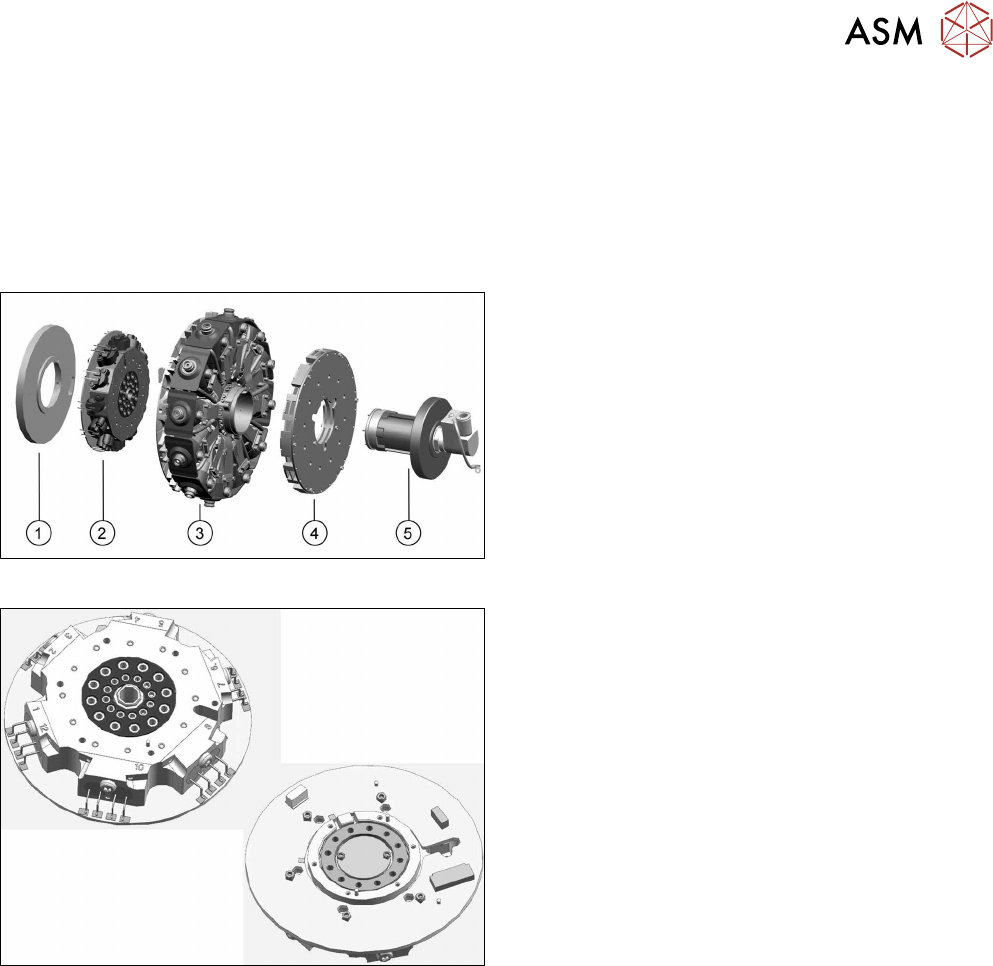
Fig.67: Star structure
1. Energy transmission for rotor
2. Valve terminal
3. Star carrier with DP drives
4. Single Core Solution (SCS).
5. Holding circuit with screwed joint
Fig.68: Valve terminal (front and back)
Valve terminal [03115167‑xx]
Preparation
► Remove the head from the machine. For details about removing and fitting the placement
head, refer to the service manual for your machine.
fit the head on the head mount [03056231‑xx].
► Make sure that the component sensor protective cap is fitted.
1.1.3 "Protecting the component sensor" [}8]
Removal (for heads from version 05)
► If required, dismantle the front plate.
5.1 "Replacing the front plate [03061102-xx]" [}35]
► Remove the star.
5.2 "Removing and fitting the star (only for heads from FS05 upwards)" [}43]
► Remove the energy transmission for the rotor.
5.6 "Replacing the energy transmission for the rotor [03068843‑xx]" [}63]
5 Front plate, star, Z axis and smoothed distributor disc
5.4 Removing the valve terminal (only for heads from FS05 upwards)
50 Service Manual SIPLACE Multistar (CPP / CPP M) 02/2018
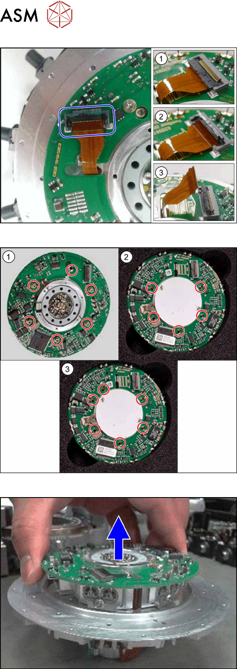
Fig.69: Flexprint cable
1. Connector closed
2. Connector open
3. Flexprint removed
► Open the connector and remove the Flexprint
cable.
Fig.70: Screws fastening the valve terminal
► Remove the screws fastening the valve terminal:
1. The old valve terminal [03082217‑xx] is fixed with
six screws to the heads up to and including
FS04.
2. The new valve terminal [03115167‑xx] is fixed
with five screws to the heads up to number [KL-
J5-0162] .
3. The new valve terminal [03115167‑xx] is fixed
with six screws to heads from number [KL-
J5-0162].
Fig.71: Removing the valve terminal
► Lift the valve terminal off the star carrier.