00197463-03_SM_CPP_Customer_EN.pdf - 第21页
2 Overview of the Modules 2.1 CPP Head Service Manual SIPLACE Multistar (CPP / CPP M) 02/2018 21 2.1.5 Holding circuit, screwed joint and silencer Overview Fig.10: Screwed joint and holding circuit with two-part silence…
2 Overview of the Modules
2.1 CPP Head
20 Service Manual SIPLACE Multistar (CPP / CPP M) 02/2018
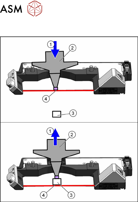
2.1.4.1 Component Sensor Functions
Fig.9: Component sensor function (example of C&P20P used)
1. Downwards (top diagram) or upwards (bottom
diagram) movement
2. Nozzle
3. Component
4. Reading out the Z position, if the laser beam is
interrupted (top diagram) or has been released
again (bottom diagram).
The component sensor signal is directly linked to the
axis controller (measurement system) of the Z axis.
This enables you to read out the Z position during up-
wards and downwards movement.
Pickup process:
When the Z axis moves downwards, the nozzle interrupts the laser beam. At this exact moment,
this Z axis position is read out and compared to the reference value, from the height reference run,
or with this segment after placement. This determines whether there is still a component on the
nozzle or not. If the Z axis position indicates that there is a component on the nozzle, the Z axis will
be immediately stopped. An error message will be issued and the component will be rejected and
sent via the repair cycle, as it will not be placed.
When the Z axis moves upwards again, the laser beam is released and the Z position recorded.
Based on the Z position during downwards movement, the system can now determine the pres-
ence and height of a component.
Placement process:
During the placement process, the system checks whether the component is on the nozzle (Z
downwards movement) or whether placement has been performed on the component (Z upwards
movement). As a precaution, these Z positions are compared to those from the pickup procedure.
This ensures maximum pickup and placement reliability.
2 Overview of the Modules
2.1 CPP Head
Service Manual SIPLACE Multistar (CPP / CPP M) 02/2018 21
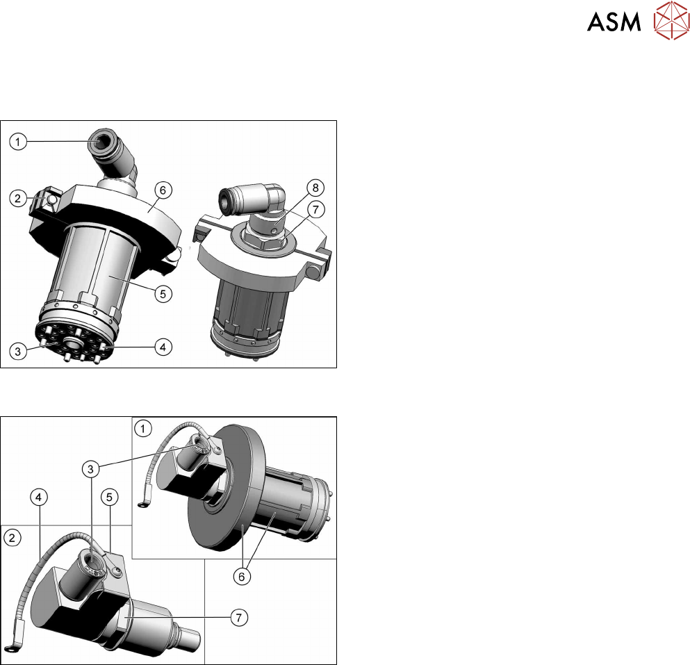
2.1.5 Holding circuit, screwed joint and silencer
Overview
Fig.10: Screwed joint and holding circuit with two-part silencer –
up to version 04
1. Compressed air inlet 4.5bar on the screwed joint
2. Retaining clips for silencer
3. Inner holes:
Venturi nozzle inlet (compressed air)
Outer holes: vacuum to the DP segments.
4. Fixture of holding circuit to star carrier
(sixscrews)
5. Holding circuit housing (plastic)
6. Two-part silencer
7. Fixture nut for the screwed joint
8. Screwed joint
Fig.11: Screwed joint and holding circuit with one-part silencer
– from version 05 (retroactively compatible)
1. Screwed joint and holding circuit housing with
one-part silencer
2. Individual screwed joint
3. Compressed air inlet 4.5bar on the screwed joint
4. Ground connection of screwed joint to the front
plate
5. Collector ring cover
6. Holding circuit housing (plastic) with one-part si-
lencer
7. Fixture nut for the screwed joint
Holding circuit
The holding circuit consists of a venturi block with two small venturi nozzles, the silencer and a
connection for the compressed air.
The compressed air inlet feeds the compressed air (min. 4.5bar) via the valves to the venturi
nozzles. Each venturi nozzle supplies a DP drive with vacuum in the holding circuit.
Depending on the head version used, there will either be a two-part or one-part holding circuit fit-
ted.
Screwed joint
The screwed joint is screwed into the holding circuit. The screwed joint is used to ensure the com-
pressed air supply to the valve terminal and to the holding circuit.
In addition, the screwed joint is fitted with a collector ring which serves as potential equalization
between the stationary and the rotating part of the placement head.
Silencer
The exhaust air from the venturi nozzles is sent via the silencer.
There are two versions of the silencer:
●
From version: one-part, together with the holding circuit
●
Up to version 04: two-part
2 Overview of the Modules
2.1 CPP Head
22 Service Manual SIPLACE Multistar (CPP / CPP M) 02/2018
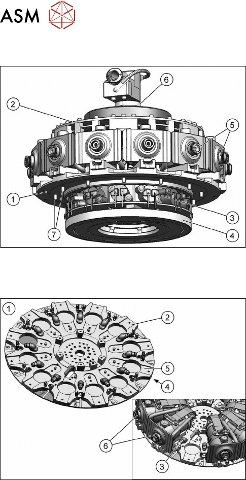
2.1.6 Star
Fig.12: Star (from FS05)
1. Star carrier
2. Single Core Solution (SCS).
3. Valve terminal
4. Contact-free energy and data transmitter
5. DP drives
6. Holding circuit in the middle of the star
7. Fixture on rotor of star motor
The star consists of the star carrier, on which all
twelve DP drives are located, the control board (SCS),
the valve terminal, an energy and a data transmitter.
The holding circuit is in the center of the star
The complete unit is fixed to the rotor of the star mo-
tor.
2.1.7 Star Frame
Fig.13: Star carrier
1. Star carrier
2. Star carrier plate
3. Hose to DP drive
4. Back of the star carrier
5. Front of the star carrier
6. DP drive
The star carrier plate is fixed directly to the rotor of the
star motor.
The valve terminal and the energy and data trans-
former are fixed to the back of the star carrier.
The twelve DP drives are fixed to the front and the
holding circuit with control unit SCS is fixed to the cen-
ter.
The air blast (component reject) and the vacuum
(component pickup) are run via the pressure control
valve, the smoothed distributor disc and the outer
valve terminal holes, through the star carrier plate via
a hose to the individual DP drives.