00197463-03_SM_CPP_Customer_EN.pdf - 第114页
9 Intermediate distributor and vacuum sensor 9.3 Replacing the vacuum sensor [03036806-xx] 114 Service Manual SIPLACE Multistar (CPP / CPP M) 02/2018 Removal Fig.188: Cover ► Turn the head over. ► Remove the four screws…
9 Intermediate distributor and vacuum sensor
9.3 Replacing the vacuum sensor [03036806-xx]
Service Manual SIPLACE Multistar (CPP / CPP M) 02/2018 113
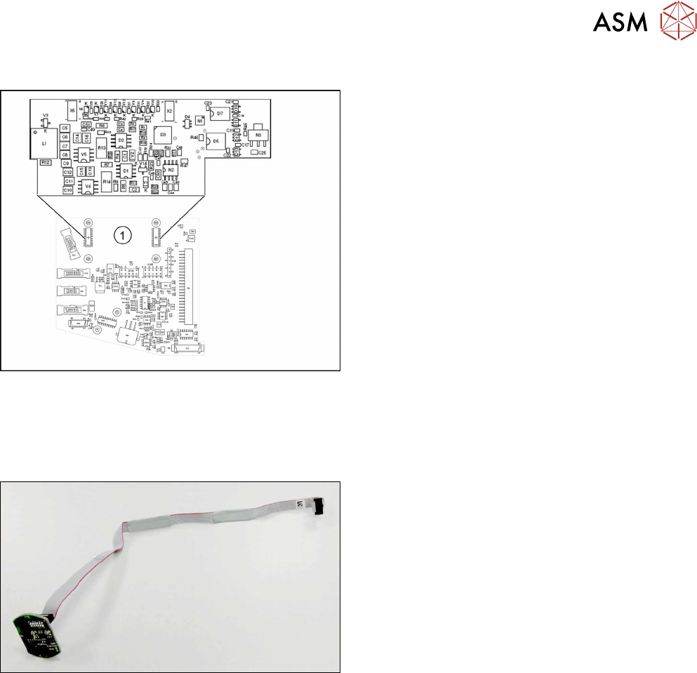
Addressing the Contactless Energy Transformer
Fig.186: KE transmitter
For contactless energy transmission an additional
board is plugged onto the intermediate distributor 2.
1. X31/X32 - KE transmitter connector terminal
Description of the LEDs:
V6 – maximum current exceeded
V7 – continuous current too high
V9 – KE control switched on
V10 – error, KE transmitter switched off
The green LED V9 lights in normal operation
9.3 Replacing the vacuum sensor [03036806-xx]
Parts, equipment and tools
Fig.187: Vacuum sensor assembly for CPP [03036806-xx]
●
Vacuum sensor assembly for CPP [03036806-xx]
Preparation
► Remove the head from the machine. For details about removing and fitting the placement
head, refer to the service manual for your machine.
fit the head on the head mount [03056231‑xx].
► Make sure that the component sensor protective cap is fitted.
1.1.3 "Protecting the component sensor" [}8]
9 Intermediate distributor and vacuum sensor
9.3 Replacing the vacuum sensor [03036806-xx]
114 Service Manual SIPLACE Multistar (CPP / CPP M) 02/2018
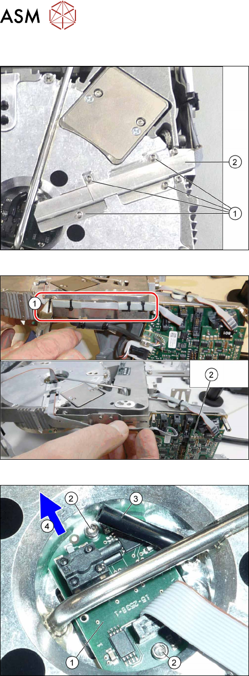
Removal
Fig.188: Cover
► Turn the head over.
► Remove the four screws (1) fastening the cover
(2) and remove the cover.
Fig.189: Cables and cable ties
► Remove the cable ties(1).
► Unthread the cable as far as the intermediate dis-
tributor2(2) and then unplug the cable.
You may want to mark the position, to make clear
assignment easier later on.
Fig.190: Vacuum sensor
► Pull the hose(3) off the vacuum sensor(1).
► Remove the two screws(2) fastening the vacuum
sensor.
► Pull the vacuum sensor and cable under the pipe
section and out, in the direction of the arrow(4).
Installation
► Follow the removal instructions in reverse order for installation.
10 Calibration
10.1 Calibrating the Heads and Cameras (SW70x)
Service Manual SIPLACE Multistar (CPP / CPP M) 02/2018 115
10 Calibration
Overview
With the calibration of the component camera the following values are determined:
the relationship of "camera pixel size to resolution of machine measuring system (X,Y)", the "cam-
era center point in X and Y direction" and the "torsion angle of the CCD sensor in the camera". This
is following by determining the head offset and the segment offsets for the top and bottom.
●
Head offset: the head offset is the distance between the PCB camera and the nozzle (seg-
ment1). The target is a fixed value (X=0 and Y=‑105mm) to which an offset value (from the
head calibration) is added.
●
Segment offset top: the top segment offset involves turning the calibration tool in the compo-
nent camera in 0°, 90°, 180° and 270°. The value determined is that of the rotating center of
the nozzle tip in relation to the component camera center in the X and Y direction.
●
Segment offset bottom: the bottom segment offset involves recording and measuring the
calibration tool in the 0°, 90°, 180° and 270° positions. The value determined is that of the ro-
tating center point of the nozzle tip when the Z axis is extended in relation to the PCB camera.
Segment1 forms the reference (X=0,Y=0) to the other segments.
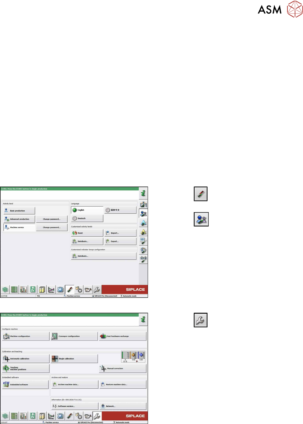
10.1 Calibrating the Heads and Cameras (SW70x)
Fig.191: Select operator level
► Click the
button to enter the Settings
menu.
► Click the
button to open the Check and set
user settings menu.
► Switch over to the operator level Machine ser-
vice.
Fig.192: Service Menu
► Click the
button to enter the Service menu.
► Click the Automatic calibration button.