00197463-03_SM_CPP_Customer_EN.pdf - 第94页
8 Screwed joint, silencer and holding circuit 8.2 Replacing the screwed joint 94 Service Manual SIPLACE Multistar (CPP / CPP M) 02/2018 Fig.158: Overview of installation points for the parts from the "Seal kit for …
8 Screwed joint, silencer and holding circuit
8.1 Overview of screwed joint, holding circuit and seals
Service Manual SIPLACE Multistar (CPP / CPP M) 02/2018 93
8 Screwed joint, silencer and holding circuit
8.1 Overview of screwed joint, holding circuit and seals
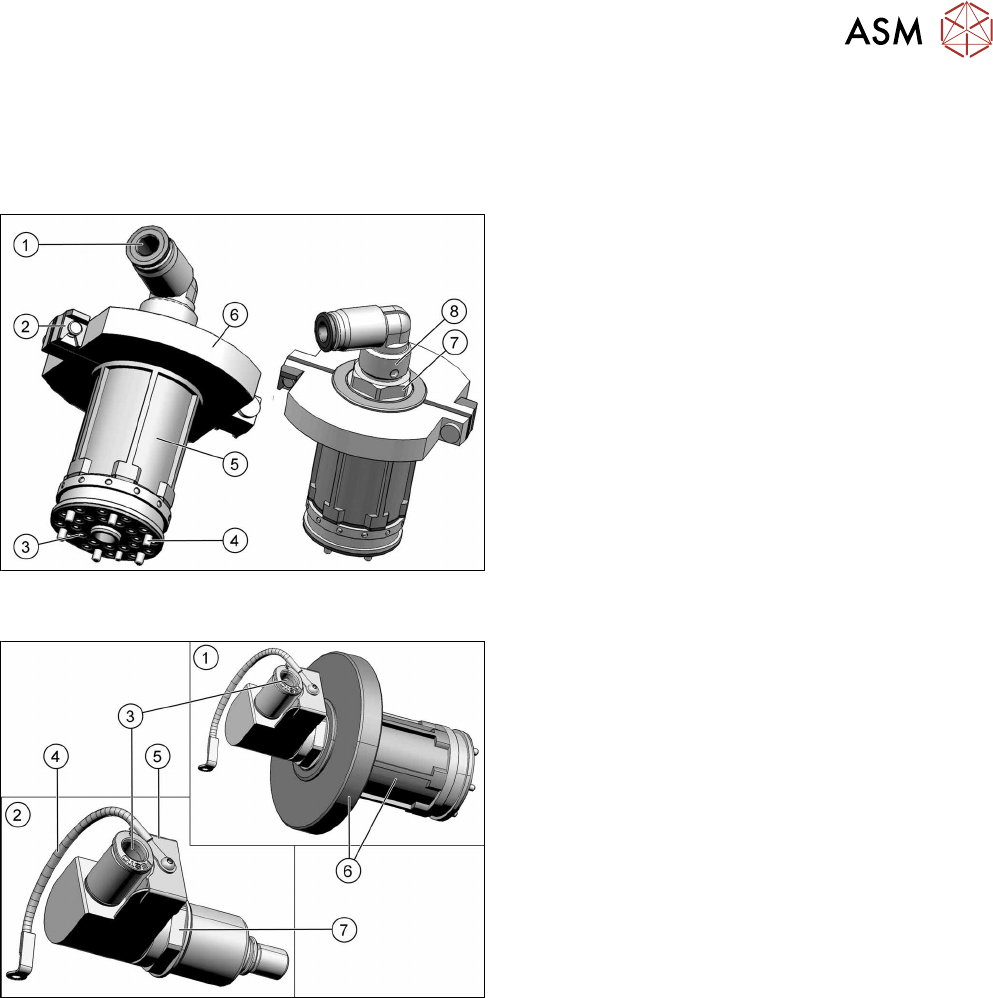
Fig.156: Screwed joint and holding circuit with two-part silencer
– up to version 04
1. Compressed air inlet 4.5bar on the screwed joint
2. Retaining clips for silencer
3. Inner holes:
Venturi nozzle inlet (compressed air)
Outer holes: vacuum to the DP segments.
4. Fixture of holding circuit to star carrier
(sixscrews)
5. Holding circuit housing (plastic)
6. Two-part silencer
7. Fixture nut for the screwed joint
8. Screwed joint
Fig.157: Screwed joint and holding circuit with one-part silencer
– from version 05 (retroactively compatible)
1. Screwed joint and holding circuit housing with
one-part silencer
2. Individual screwed joint
3. Compressed air inlet 4.5bar on the screwed joint
4. Ground connection of screwed joint to the front
plate
5. Collector ring cover
6. Holding circuit housing (plastic) with one-part si-
lencer
7. Fixture nut for the screwed joint
8 Screwed joint, silencer and holding circuit
8.2 Replacing the screwed joint
94 Service Manual SIPLACE Multistar (CPP / CPP M) 02/2018
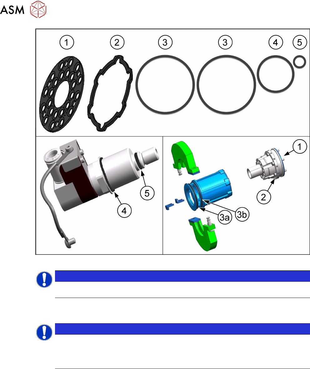
Fig.158: Overview of installation points for the parts from the "Seal kit for holding circuit CPP" [03095007‑xx]
NOTICE
The seals(3) for the two-part silencer are no longer needed when using the one-part silen-
cer.
8.2 Replacing the screwed joint
NOTICE
Observe the head version
Different screwed joints are used for the SIPLACE CPP heads up to version 04 and those
from version 05 onwards.
Relevant differences for removal and installation work will be mentioned.
Parts, equipment and tools
●
Select the required screwed joint:
– Up to version 04: screwed joint assembly CPP [03080101-xx]
– From version 05: screwed joint assembly CPP [03080144‑xx]
Replace any defective seals, where required:
●
Seal kit for holding circuit / CPP [03095007‑xx]
Keep any seals which are not needed.
Overview
► Observe the following section:
8.1 "Overview of screwed joint, holding circuit and seals" [}93]
8 Screwed joint, silencer and holding circuit
8.2 Replacing the screwed joint
Service Manual SIPLACE Multistar (CPP / CPP M) 02/2018 95
Preparation
► Remove the head from the machine. For details about removing and fitting the placement
head, refer to the service manual for your machine.
fit the head on the head mount [03056231‑xx].
► Make sure that the component sensor protective cap is fitted.
1.1.3 "Protecting the component sensor" [}8]
Removal
► If required, dismantle the front plate.
5.1 "Replacing the front plate [03061102-xx]" [}35]
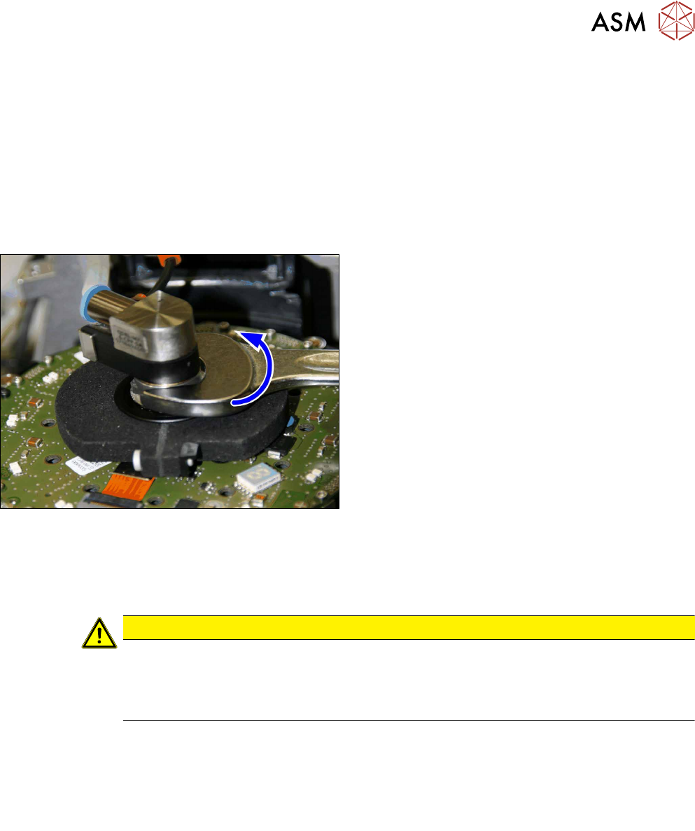
Fig.159: Screwed joint
► Unscrew the fixture nut for the screwed joint until
you can remove the screwed joint.
► Remove the screwed joint together with the hold-
ing circuit housing and one-part silencer.
Installation
► Follow the removal instructions in reverse order for installation. Also observe the following in-
structions:
CAUTION
Installation instructions
► Insert the screwed joint and hand-tighten the fixture nut for the screwed joint.
► Up to version 04 only: Always attach the retaining clips for the silencer from above.
If these are fitted from the side, the seals(3a) and (3b) might be damaged.
All versions:
► Observe the installation instructions in the following sections:
8.3.3 "Replacing the silencer" [}97]
5.1 "Replacing the front plate [03061102-xx]" [}35]
► Observe in particular the torques specified!
See also
2 8.3 "Silencer" [}96]