00197463-03_SM_CPP_Customer_EN.pdf - 第34页
4 Component camera and component sensor 4.3 Replacing the component sensor cable [03063595-xx] 34 Service Manual SIPLACE Multistar (CPP / CPP M) 02/2018
4 Component camera and component sensor
4.3 Replacing the component sensor cable [03063595-xx]
Service Manual SIPLACE Multistar (CPP / CPP M) 02/2018 33
4.3 Replacing the component sensor cable [03063595-xx]
Parts, equipment and tools
●
Component sensor CPP [03063595‑xx]
Overview
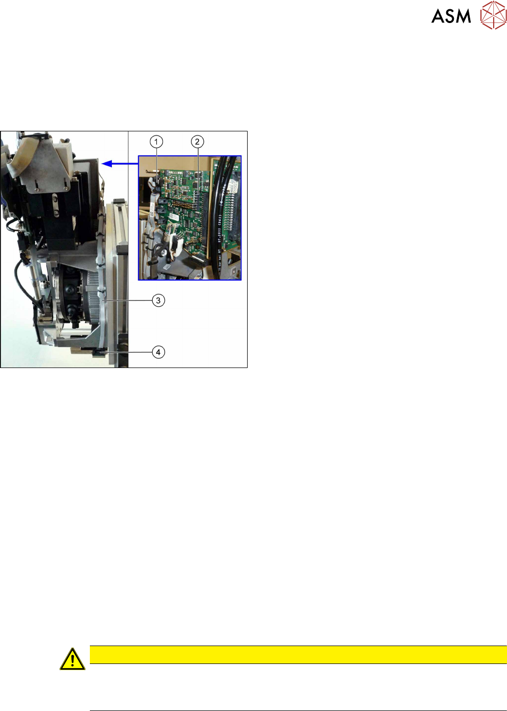
Fig.33: Component sensor cable
1. Plug for intermediate distributor2 (ID2)
2. Intermediate distributor 2 with KE control board
ID2 (rucksack board)
See also 9.2 "Replacing Intermediate Distributors
1 and 2" [}107]
3. Cable to component sensor
4. Connector on component sensor
Preparation
► Remove the head from the machine. For details about removing and fitting the placement
head, refer to the service manual for your machine.
fit the head on the head mount [03056231‑xx].
► Make sure that the component sensor protective cap is fitted.
1.1.3 "Protecting the component sensor" [}8]
Removal
► Unplug the connector from the component sensor by pressing the sides of it together slightly.
This releases the catch in the connector.
► Using the same procedure, unplug the connector (X21) from ID2.
► Remove all relevant cable ties. You may want to mark their positions for easier exact replace-
ment later on.
► Remove the cable.
Installation
► Follow the removal instructions in reverse order for installation. Also observe the following in-
structions:
CAUTION
Installation instructions
► Fasten the cable with cable ties.
► Make sure that the cable is run correctly.

4 Component camera and component sensor
4.3 Replacing the component sensor cable [03063595-xx]
34 Service Manual SIPLACE Multistar (CPP / CPP M) 02/2018
5 Front plate, star, Z axis and smoothed distributor disc
5.1 Replacing the front plate [03061102-xx]
Service Manual SIPLACE Multistar (CPP / CPP M) 02/2018 35
5 Front plate, star, Z axis and smoothed
distributor disc
5.1 Replacing the front plate [03061102-xx]
Parts, equipment and tools
●
Front plate with Z drive assembly CPP [03061102-xx]
Overview
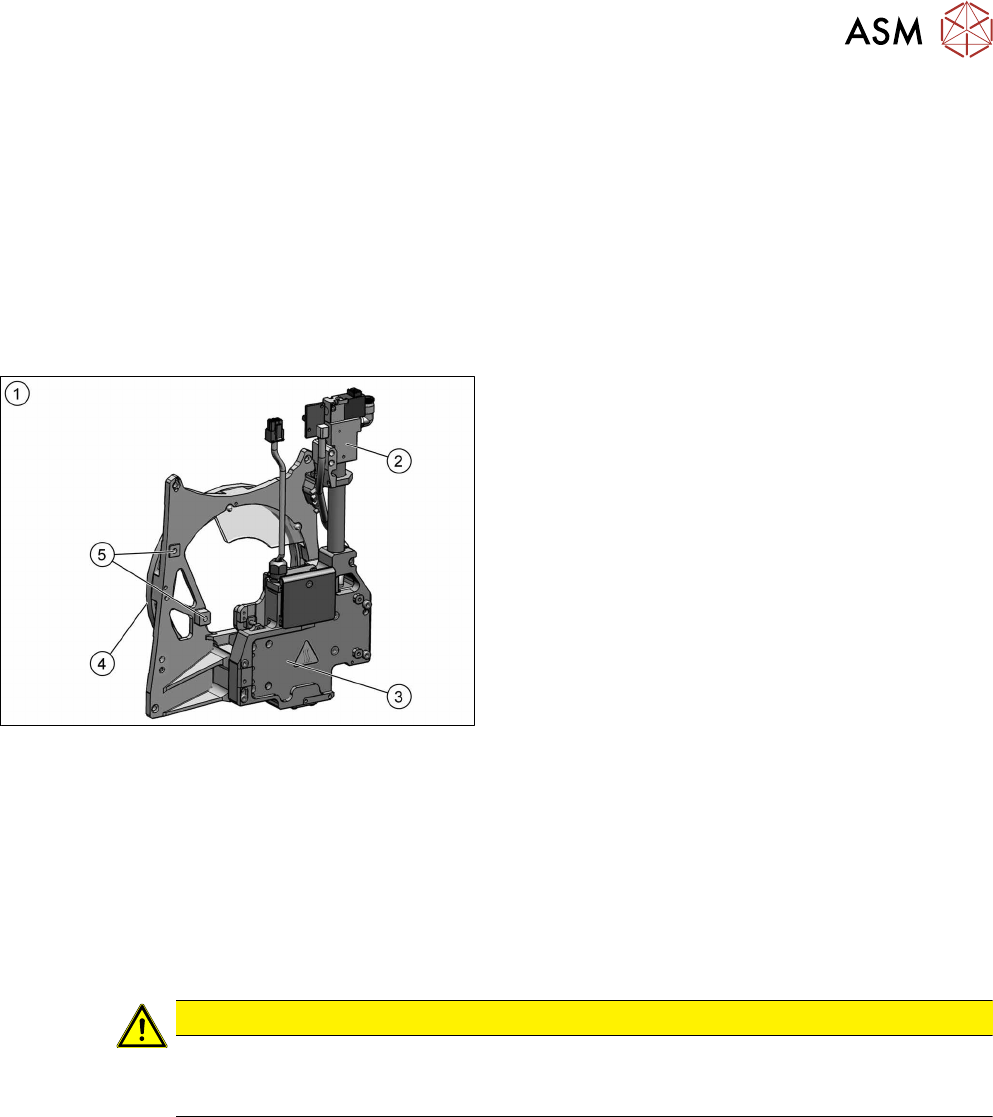
Fig.34: Front plate
1. Front plate
2. Return cylinder
3. Z axis with jaws and measuring system
4. Raceway
5. Fixture for pressure control valve
Preparation
► Remove the head from the machine. For details about removing and fitting the placement
head, refer to the service manual for your machine.
fit the head on the head mount [03056231‑xx].
► Make sure that the component sensor protective cap is fitted.
1.1.3 "Protecting the component sensor" [}8]
Removal
CAUTION
Do not dismantle any attachments
Do not dismantle any of the attachments from the front plate, as all attachments are co-
ordinated with one another and require special settings.