00197463-03_SM_CPP_Customer_EN.pdf - 第106页
9 Intermediate distributor and vacuum sensor 9.1 Replacing the KE Control Board ZV2 [03073355-xx] 106 Service Manual SIPLACE Multistar (CPP / CPP M) 02/2018 Preparation ► Remove the head from the machine. For details abo…
9 Intermediate distributor and vacuum sensor
9.1 Replacing the KE Control Board ZV2 [03073355-xx]
Service Manual SIPLACE Multistar (CPP / CPP M) 02/2018 105
9 Intermediate distributor and vacuum sensor
9.1 Replacing the KE Control Board ZV2 [03073355-xx]
Parts, equipment and tools
●
KE control board ID2 [03073355-xx]
Overview
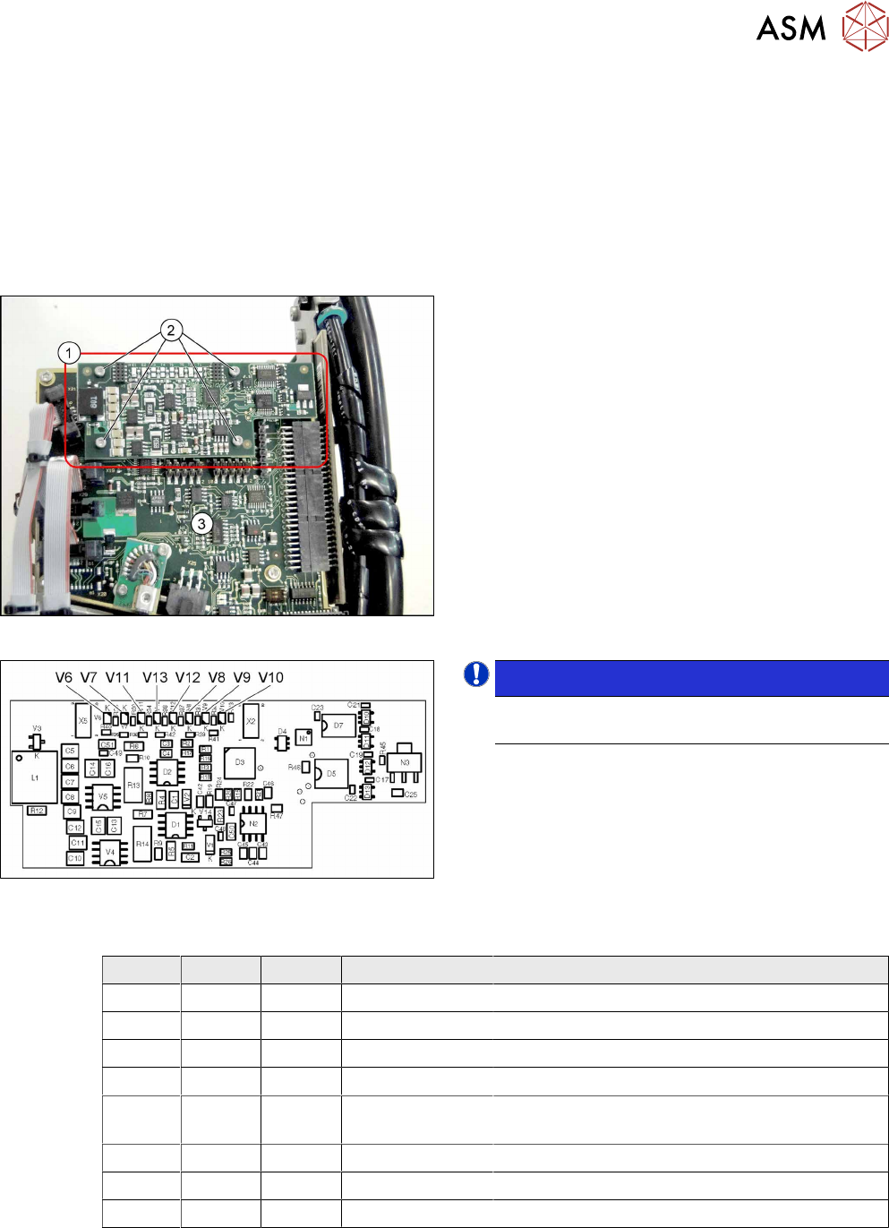
Fig.179: KE control board ID2
1. KE control board ID2
2. Fastening screws for KE control board ID2
3. Intermediate distributor 2 (ID2)
Fig.180: 03073355-02
NOTICE!
The "KE control board ID2" is only used for CPP
heads from version 05 onwards.
.
LED [03073355-02]
LED Color Status Signal name Description
V6 RD ON D3/BANK2/IO[1] Maximum current exceeded
V7 RD ON D3/BANK1/IO[36] Continuous current too high
V8 GN - FPGA_TEST_2 Not used
V9 GN ON FPGA_TEST_4 KE control switched on
V10 RD ON STATUS_24V_D
P
KE transmitter error switched off
V11 GN - FPGA_TEST_5 Not used
V12 GN - FPGA_TEST_1 Not used
V13 GN - FPGA_TEST_3 Not Used

9 Intermediate distributor and vacuum sensor
9.1 Replacing the KE Control Board ZV2 [03073355-xx]
106 Service Manual SIPLACE Multistar (CPP / CPP M) 02/2018
Preparation
► Remove the head from the machine. For details about removing and fitting the placement
head, refer to the service manual for your machine.
fit the head on the head mount [03056231‑xx].
► Make sure that the component sensor protective cap is fitted.
1.1.3 "Protecting the component sensor" [}8]
Removal
► Remove the screwsfastening the board.
► Carefully pull the board off the ID2. Pay particular attention to the connectors on the underside
of the board.
Installation
► Follow the removal instructions in reverse order for installation. Also observe the following in-
structions:
CAUTION
Installation instructions
► Make sure that you do not damage the connectors on the underside of the board.
9 Intermediate distributor and vacuum sensor
9.2 Replacing Intermediate Distributors 1 and 2
Service Manual SIPLACE Multistar (CPP / CPP M) 02/2018 107
9.2 Replacing Intermediate Distributors 1 and 2
NOTICE
Same procedure
The procedure is the same for ID 1 and ID2. Any relevant differences will be mentioned.
Parts, equipment and tools
●
Select the part required:
– Board ID1 (intermediate distributor1)
CPP: [03065295‑xx]
CPP M: [03155680‑xx]
– Board ID2 (intermediate distributor2)
CPP / CPP M: [03052586‑xx]
Overview
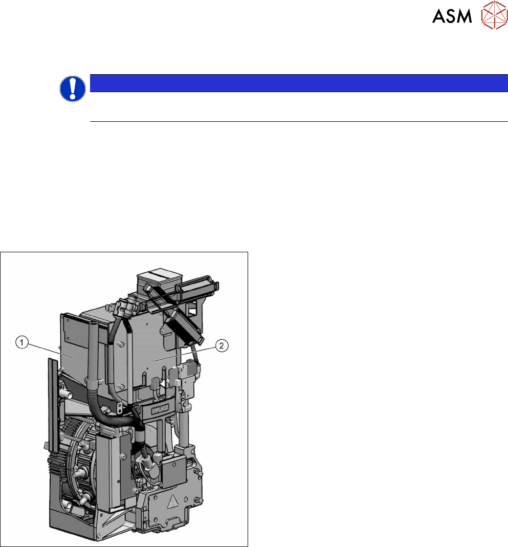
Fig.181: Intermediate distributor 1 and 2
The intermediate distributor (ID) consists of two
boards:
1. The ID1 is fitted to the front side of the head.
2. The ID2 incl. "KE control board ID2" (rucksack
board) is fitted on the left, to the side of the head.
Description of boards:
●
9.2.1 "Intermediate distributor ZV1/CPP
[03065295-xx] " [}110]
●
9.2.2 "Intermediate distributor ZV2/CPP
[03052586-xx] " [}111]
Intermediate distributor function:
●
LEDs show the operating voltages at the head
and the sensor states
●
Test connector for the track signals and test pins
for analog signals
●
Controlled power supply for incremental encoder
from Z and star drive
●
Interface for component sensor, vacuum unit, va-
cuum sensor of holding circuit and EEPROM
●
Startup control for the return cylinder