00197463-03_SM_CPP_Customer_EN.pdf - 第83页
7 Pressure control valve (PRV) 7.3 Replacing the cable on the PRV [03063596‑xx] Service Manual SIPLACE Multistar (CPP / CPP M) 02/2018 83 7.3 Replacing the cable on the PRV [03063596‑xx] Parts, equipment and tools ● Cabl…
7 Pressure control valve (PRV)
7.2 Calibrating the digital PRV
82 Service Manual SIPLACE Multistar (CPP / CPP M) 02/2018
7.2 Calibrating the digital PRV
The digital PRV is part of the placement head and generates the vacuum and the blast air for the
pickup and placement process. The zero point calibration of the digital PRV must be performed on
initial startup by the customer and then checked again after replacement of the digital PRV or the
placement head and recalibrated if necessary.
The zero point calibration is used to set the motor in the digital PRV into a neutral or central posi-
tion so that there is no vacuum or air blast at the nozzle.
7.2.1 Zero Point Calibration of Pressure Control Valve
NOTICE
From SW706 this function is performed automatically (automatic calibration menu).
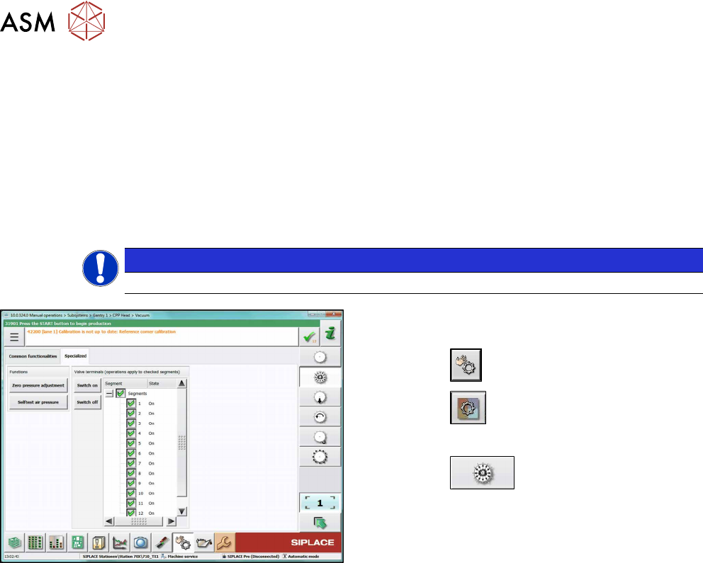
Fig.126: Set pressure to zero (SW710, example of SIPLACE
CPP)
► Switch over to operator level SIPLACE (cus-
tomer).
► Click the
button.
► Click the
button.
► Select the placement head.
► Click the
button.
► Go to the Specializedtab.
► Click on the Zero pressure adjustmentbutton.
7 Pressure control valve (PRV)
7.3 Replacing the cable on the PRV [03063596‑xx]
Service Manual SIPLACE Multistar (CPP / CPP M) 02/2018 83
7.3 Replacing the cable on the PRV [03063596‑xx]
Parts, equipment and tools
●
Cable from intermediate distributor (ID2) to pressure control valve of the CPP [03063596-xx]
Overview
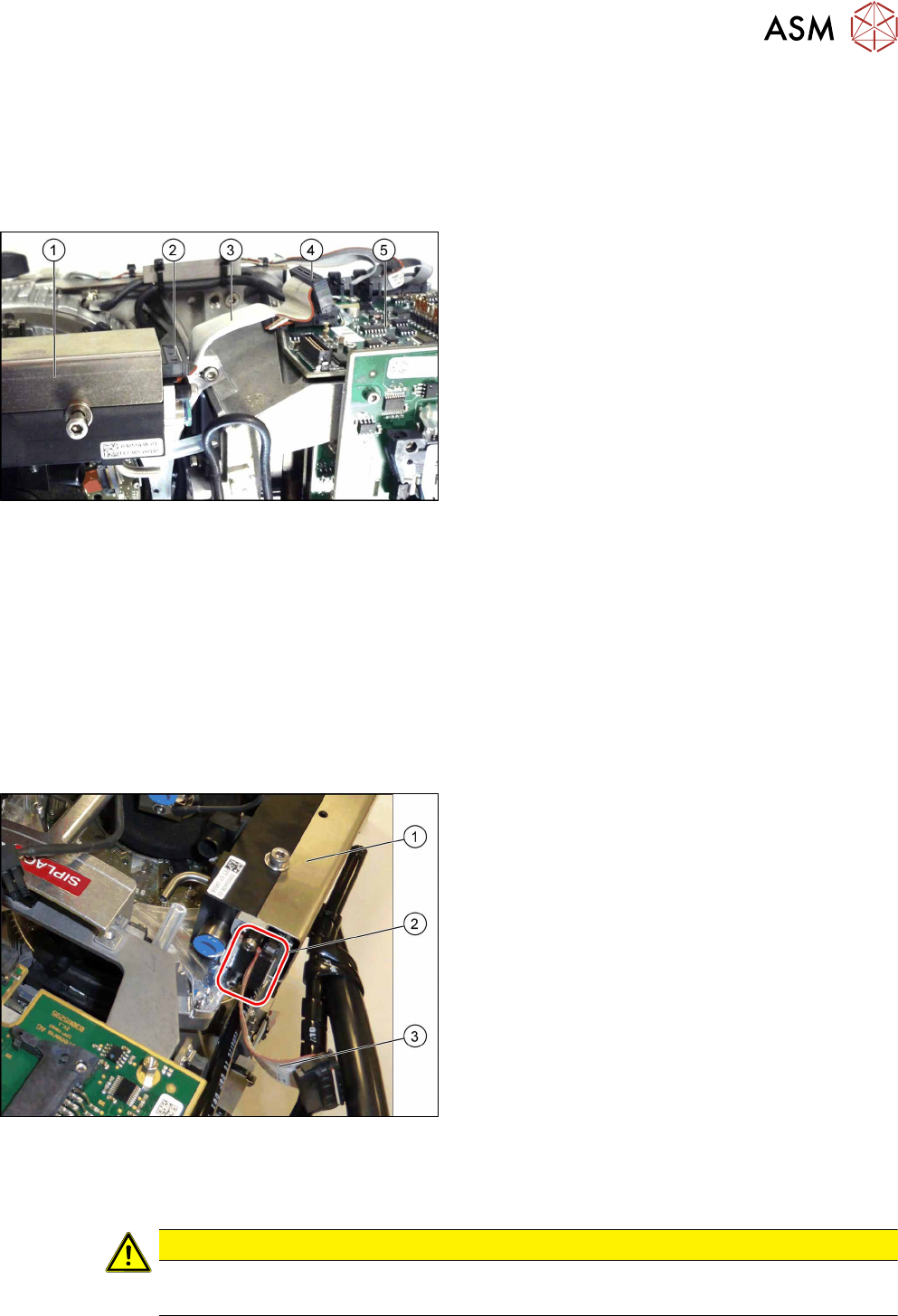
Fig.127: Pressure control valve (PRV)
1. Pressure control valve (PRV)
2. Connector on pressure control valve
3. Cable [03063596‑xx]
4. Connector on ID2
5. ID2
Preparation
► Remove the head from the machine. For details about removing and fitting the placement
head, refer to the service manual for your machine.
fit the head on the head mount [03056231‑xx].
► Make sure that the component sensor protective cap is fitted.
1.1.3 "Protecting the component sensor" [}8]
Removal
► Unplug the cable connector from ID2. Press the connector slightly at the sides to release the
lock.
1. PRV
2. Strain relief with two fastening screws and con-
nector
3. Cable [03063596‑xx]
► Remove the two screws fastening the strain re-
lief(2) and then remove the strain relief.
► Unplug the cable connector from the PRV. Press
the connector slightly at the sides to release the
lock.
Installation
► Follow the removal instructions in reverse order for installation. Also observe the following in-
structions:
CAUTION
Installation instructions
► When attaching, press the connector slightly at the sides to release the catch.
7 Pressure control valve (PRV)
7.4 Replacing small parts on the PRV
84 Service Manual SIPLACE Multistar (CPP / CPP M) 02/2018
7.4 Replacing small parts on the PRV
NOTICE
Example
The replacement is illustrated with the example of the pressure control valve (PRV) for the
SIPLACE Twin Head. The procedure is the same for other PRVs.
Parts, equipment and tools
Select the required spare part:
●
Self-tapping screws:
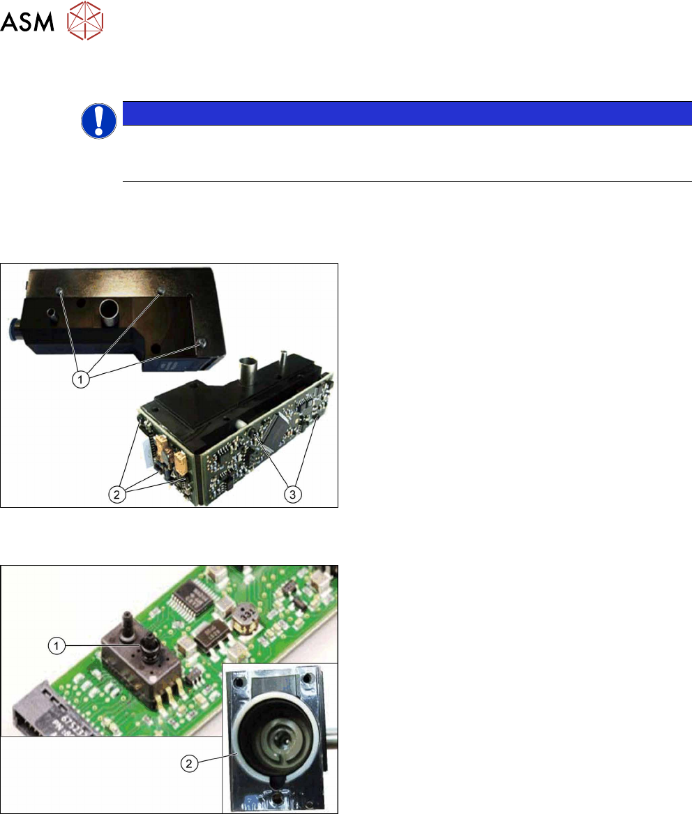
Fig.128: Screws
1. Self-tapping screw PT-WN1442-2.5X6-PT10
[03119666‑xx]
Self-tapping screw PT-WN1413-2.5X6-PT10
[03119678‑xx]
2. Self-tapping screw PT-WN1442-2.5X8-PT10
[03119677‑xx]
3. Self-tapping screw PT-WN1412-2.5X14-PT10
[03119676‑xx]
●
O-ring / centering ring:
Fig.129: O-ring / centering ring:
1. O-ring I3601 B-1.5X1.08-N-NBR70
[03119672‑xx]
2. Centering ring VADI-MPPE-QS6-24VDC–SA
[03119675‑xx]
●
Distance sleeve: