00197902-03_UM_X-Serie-S_EN.pdf - 第158页
3 Technical data and assemblies User manual SIPLACE X-Series 3.6 Gantry system From software version 710.0 Edition 12/2016 158 3.6.3 Position of gant ries in SIPLACE X3 S 3 Fig. 3.6 - 3 Position of gantries - SIPLACE X3 …
User manual SIPLACE X-Series 3 Technical data and assemblies
From software version 710.0 Edition 12/2016 3.6 Gantry system
157
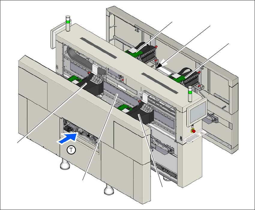
3.6.2 Position of gantries in SIPLACE X4 S / X4 S micron
3
Fig. 3.6 - 2 Position of gantries in SIPLACE X4 S / X4 S micron
(1) Y axis, gantry 1 and gantry 4
(2) X axis, gantry 1
(3) X axis, gantry 2
(4) Y axis, gantry 3 and gantry 4 (concealed)
(5) X axis, gantry 3
(6) X axis, gantry 4
(T) Direction of PCB transport
(1)
(3)
(6)
(4)
(2)
(5)
3 Technical data and assemblies User manual SIPLACE X-Series
3.6 Gantry system From software version 710.0 Edition 12/2016
158
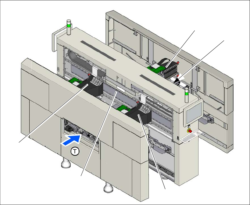
3.6.3 Position of gantries in SIPLACE X3 S
3
Fig. 3.6 - 3 Position of gantries - SIPLACE X3 S
(1) Y axis, gantry 1 and gantry 4
(2) X axis, gantry 1
(3) X axis, gantry 3 (covered)
(4) X axis, gantry 3
(5) X axis, gantry 4
(T) Direction of PCB transport
(1)
(5)
(3)
(2)
(4)
User manual SIPLACE X-Series 3 Technical data and assemblies
From software version 710.0 Edition 12/2016 3.6 Gantry system
159
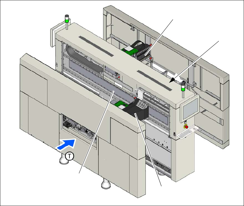
3.6.4 Position of gantries in SIPLACE X2 S
3
Fig. 3.6 - 4 Position of gantries - SIPLACE X2 S
(1) Y axis, gantry 1
(2) X axis, gantry 1
(3) X axis, gantry 2 (covered)
(4) X axis, gantry 2
(T) Direction of PCB transport
(1)
(3)
(2)
(4)