00197902-03_UM_X-Serie-S_EN.pdf - 第371页
User manual SIPLACE X-Series 6 Station extensions From software version 710.0 Ed ition 12/2016 6.8 Docking station for the component trolley of the SIPLACE X-Series 371 6 Fig. 6.8 - 2 Docking station - dimensio ns in mil…

6 Station extensions User manual SIPLACE X-Series
6.8 Docking station for the component trolley of the SIPLACE X-Series From software version 710.0 Edition 12/2016
370
Legend for fig. 6.8 - 1, page 369
(1) Docking station
(2) X-Series COT insert
(3) Protective plate with warning sign W204
(4) Rails for guiding and docking the changeover table
(5) Clamping lever for locking the component trolley
(6) EDIF (energy and data interface)
The main tasks performed by the docking station are as follows:
– Supply of energy to the component trolley and X feeder modules
– Supply of compressed air to the component trolley and X feeder modules
– Provision of an infrastructure for communication between the pre-setup location PC and
the feeder modules
With the help of the docking station, the operator can perform function tests to the X feeder mod-
ules outside the production environment and can check the setup. There are two rows, each with
four docking stations, connected via the CAN bus of the pre-setup PC. Each docking station has
its own power and compressed air connection.
The COT insert (item 2 in fig. 6.8 - 1
, page 369) for the docking station can be adjusted to the
required PCB conveyor height. To perform the pre-setup tasks, the component trolley is pushed
into the docking station (item 1 in fig. 6.8 - 1
, page 369). The component trolley slides along the
docking unit rails, with the roller bearings on the side of the component trolley, up to the energy
and data interface connection. The changeover table with the feeder module EDIF is positioned
precisely in relation to the EDIF (item 5 in fig. 6.8 - 1
, page 369) of the COT insert and fixed in this
position with the two clamping levers. The protective plates (item 3 in fig. 6.8 - 1
, page 369) pre-
vent access to the component trolley rollers, once these are pushed into the docking station.
User manual SIPLACE X-Series 6 Station extensions
From software version 710.0 Edition 12/2016 6.8 Docking station for the component trolley of the SIPLACE X-Series
371
6
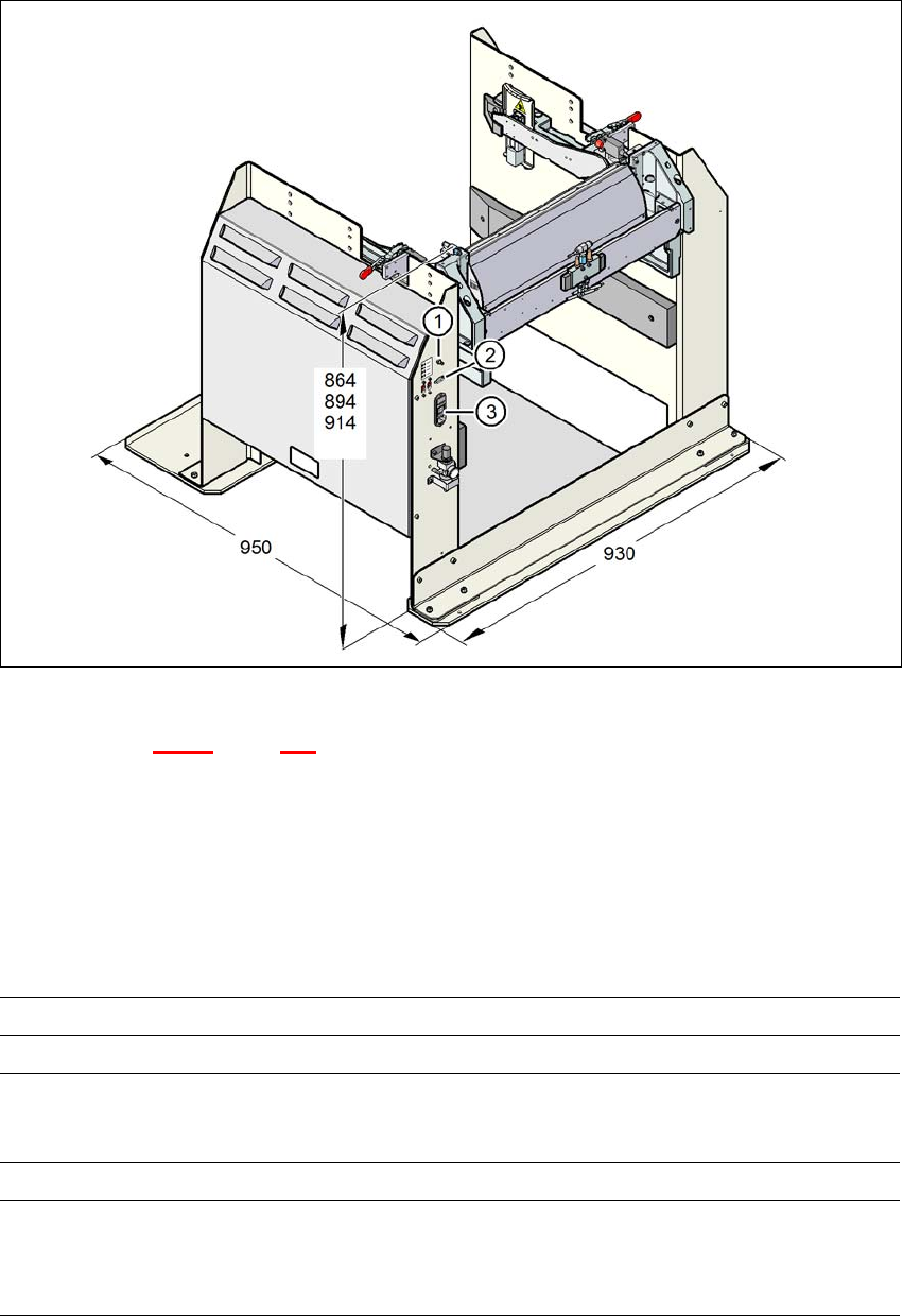
Fig. 6.8 - 2 Docking station - dimensions in millimeters, connection points
Legend for fig. 6.8 - 2, page 371
(1) Compressed air connection
(2) CAN bus connection
(3) Power supply connection
6.8.2 Technical data
6
Dimensions
Length x width 950 mm x 930 mm
Height 864 mm for 900 mm PCB conveyor height
894 mm for 930 mm PCB conveyor height
914 mm for 950 mm PCB conveyor height
Weight 120 kg
Compressed air pressure val-
ues
p
min
p
max
0.5 MPa (5.0 bar)
1.0 MPa (10.0 bar)
6 Station extensions User manual SIPLACE X-Series
6.8 Docking station for the component trolley of the SIPLACE X-Series From software version 710.0 Edition 12/2016
372
6
6
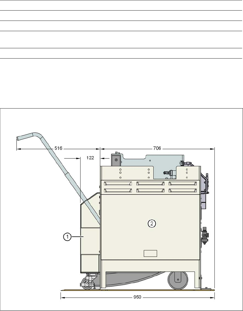
6.8.3 Dimensions of docking station with docked component trolley
6
Fig. 6.8 - 3 Docking station with docked component trolley - dimensions in millimeters
(1) Component trolley
(2) Docking station
Compressed air connection Connection plug KS 2-M5-A
Compressed air consumption 50 Nl/min
*a
Supply voltage 88 - 264 V~
Rated current 3.5 A (230 V~)
7 A (115 V~)
Performance 0.8 kW
*)a Under normal atmospheric conditions at 20°C and 1013 hPa