00197902-03_UM_X-Serie-S_EN.pdf - 第369页
User manual SIPLACE X-Series 6 Station extensions From software version 710.0 Ed ition 12/2016 6.8 Docking station for the component trolley of the SIPLACE X-Series 369 6.8 Docking st ation for the component trolley of t…
6 Station extensions User manual SIPLACE X-Series
6.7 Fixed component table for tray feeders From software version 710.0 Edition 12/2016
368
6.7 Fixed component table for tray feeders
Item no. 00519990-xx Fixed component table for tray feeders
This component table is a fixed installation at the location and is required for use of the following
feeders:
– SIPLACE JTF-S
– SIPLACE JTF-M
It has room for a JTF-S or a JTF-M. The fixed component table can be fitted at location 2 and /or
location 3.
6
6
WARNING
Free locations with dummy feeder modules
Free locations need to be occupied with dummy feeders.
PLEASE NOTE
For more information, refer to the "User Manual JTF-S/JTF-M", German+English [Item
No. 00197446-xx]
User manual SIPLACE X-Series 6 Station extensions
From software version 710.0 Edition 12/2016 6.8 Docking station for the component trolley of the SIPLACE X-Series
369
6.8 Docking station for the component trolley of the
SIPLACE X-Series
Item no. 00116933-xx Docking station for SIPLACE X component trolley
6
6.8.1 Description
The docking station is an additional component for the setup area. It forms the link between the
setup area and the component trolley for the SIPLACE X-Series. The docking station allows the
component trolleys to be set up with feeder modules and function tests and setup checks to be
carried out externally.
6
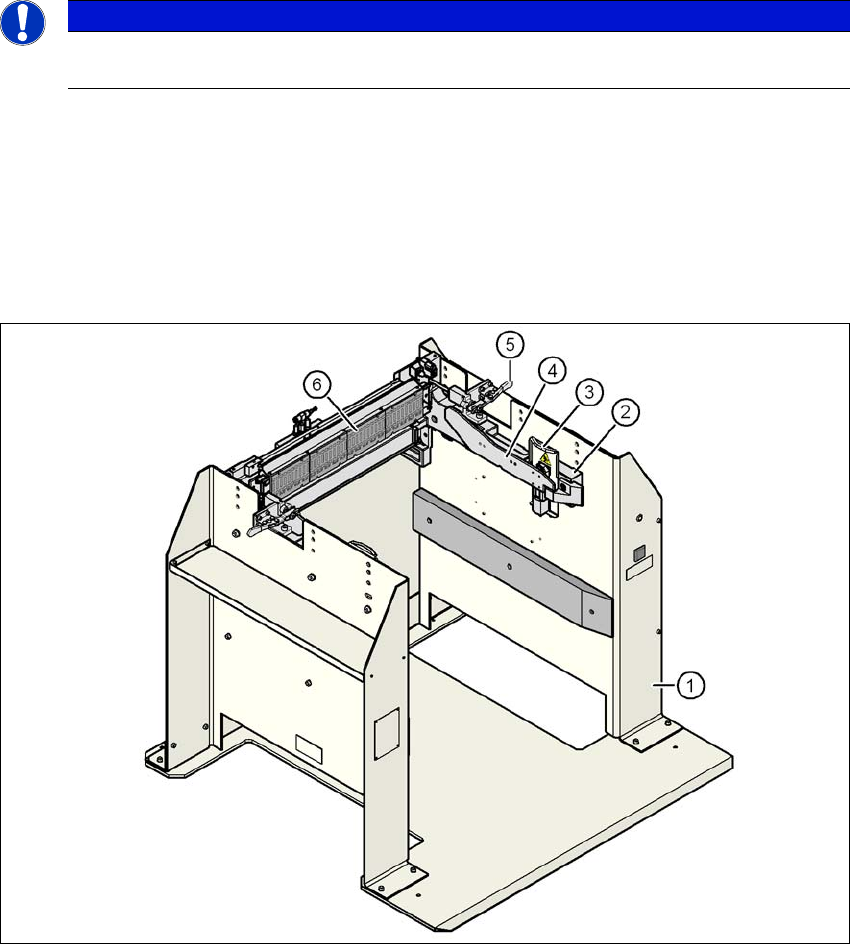
Fig. 6.8 - 1 Docking station, SIPLACE X-Series
PLEASE NOTE
A docking station (multi docking station) with which component trolleys can be config-
ured for 30, 40 and 60 tracks , is available on request.

6 Station extensions User manual SIPLACE X-Series
6.8 Docking station for the component trolley of the SIPLACE X-Series From software version 710.0 Edition 12/2016
370
Legend for fig. 6.8 - 1, page 369
(1) Docking station
(2) X-Series COT insert
(3) Protective plate with warning sign W204
(4) Rails for guiding and docking the changeover table
(5) Clamping lever for locking the component trolley
(6) EDIF (energy and data interface)
The main tasks performed by the docking station are as follows:
– Supply of energy to the component trolley and X feeder modules
– Supply of compressed air to the component trolley and X feeder modules
– Provision of an infrastructure for communication between the pre-setup location PC and
the feeder modules
With the help of the docking station, the operator can perform function tests to the X feeder mod-
ules outside the production environment and can check the setup. There are two rows, each with
four docking stations, connected via the CAN bus of the pre-setup PC. Each docking station has
its own power and compressed air connection.
The COT insert (item 2 in fig. 6.8 - 1
, page 369) for the docking station can be adjusted to the
required PCB conveyor height. To perform the pre-setup tasks, the component trolley is pushed
into the docking station (item 1 in fig. 6.8 - 1
, page 369). The component trolley slides along the
docking unit rails, with the roller bearings on the side of the component trolley, up to the energy
and data interface connection. The changeover table with the feeder module EDIF is positioned
precisely in relation to the EDIF (item 5 in fig. 6.8 - 1
, page 369) of the COT insert and fixed in this
position with the two clamping levers. The protective plates (item 3 in fig. 6.8 - 1
, page 369) pre-
vent access to the component trolley rollers, once these are pushed into the docking station.