00197902-03_UM_X-Serie-S_EN.pdf - 第375页
User manual SIPLACE X-Series 6 Station extensions From software version 710.0 Ed ition 12/2016 6.8 Docking station for the component trolley of the SIPLACE X-Series 375 6.8.5 Adjusting the docking st at ion to the PCB co…

6 Station extensions User manual SIPLACE X-Series
6.8 Docking station for the component trolley of the SIPLACE X-Series From software version 710.0 Edition 12/2016
374
Legend for fig. 6.8 - 4
, page 373.
(1) Button with control lamp for mains power supply
(2) Button for locking and unlocking all feeder modules on the component trolley
(3) Clamping lever for fastening the changeover table - lever in position "closed"
(4) Label with diagram of switch S1 and S2 for addressing the CAN bus
(5) Switch S1 and S2 for setting the CAN bus address
(6) Mains switch
(7) Rotary knob for setting the operating pressure
(8) Manometer for showing the operating pressure
User manual SIPLACE X-Series 6 Station extensions
From software version 710.0 Edition 12/2016 6.8 Docking station for the component trolley of the SIPLACE X-Series
375
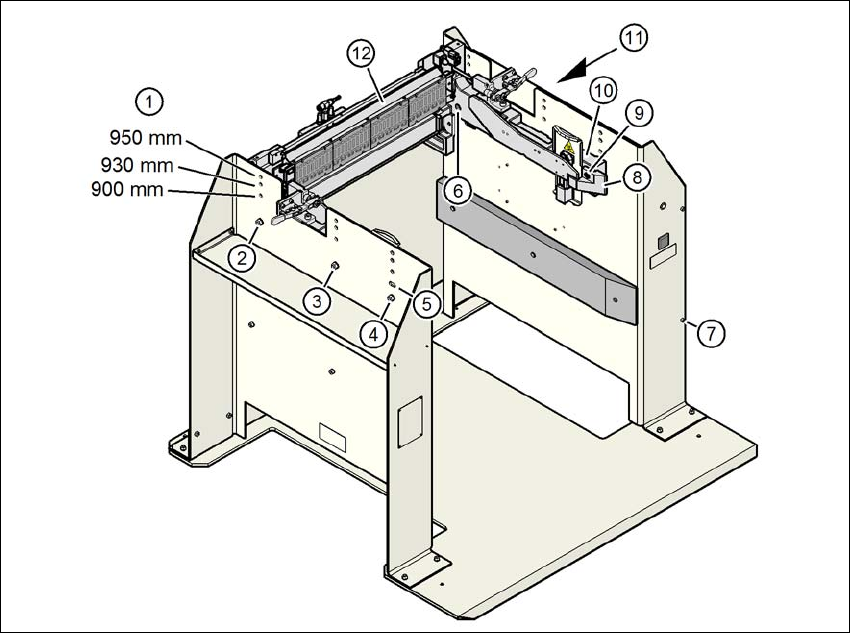
6.8.5 Adjusting the docking station to the PCB conveyor height
The COT insert of the docking station can be easily converted to PCB conveyor heights of 900,
930 and 950 mm.
6
Fig. 6.8 - 5 Adjusting the COT insert to the PCB conveyor heights
(1) Holes for the PCB conveyor height
(2) Hexagonal nut M8 and washer, 2x each
(3) Hexagonal nut M8 and washer, 2x each
(4) Hexagonal nut M8 and washer, 2x each
(5) Slot for height adjustment
(6) Hexagon socket-head screw M8x40, 6x
(7) Hexagon socket-head screw M5x12, 4x
(8) Guidance
(9) Hexagon socket-head screw M8x18, 2x
(10) Side panel, COT insert
(11) Cover on docking station
(12) Feeder module control unit (FCU)
6 Station extensions User manual SIPLACE X-Series
6.8 Docking station for the component trolley of the SIPLACE X-Series From software version 710.0 Edition 12/2016
376
6.8.5.1 Tools
You will need the following tools to adjust the height of the COT insert:
– Allen wrench, set
– Fork wrench, SW 13
6.8.5.2 Converting the COT insert to other heights
6
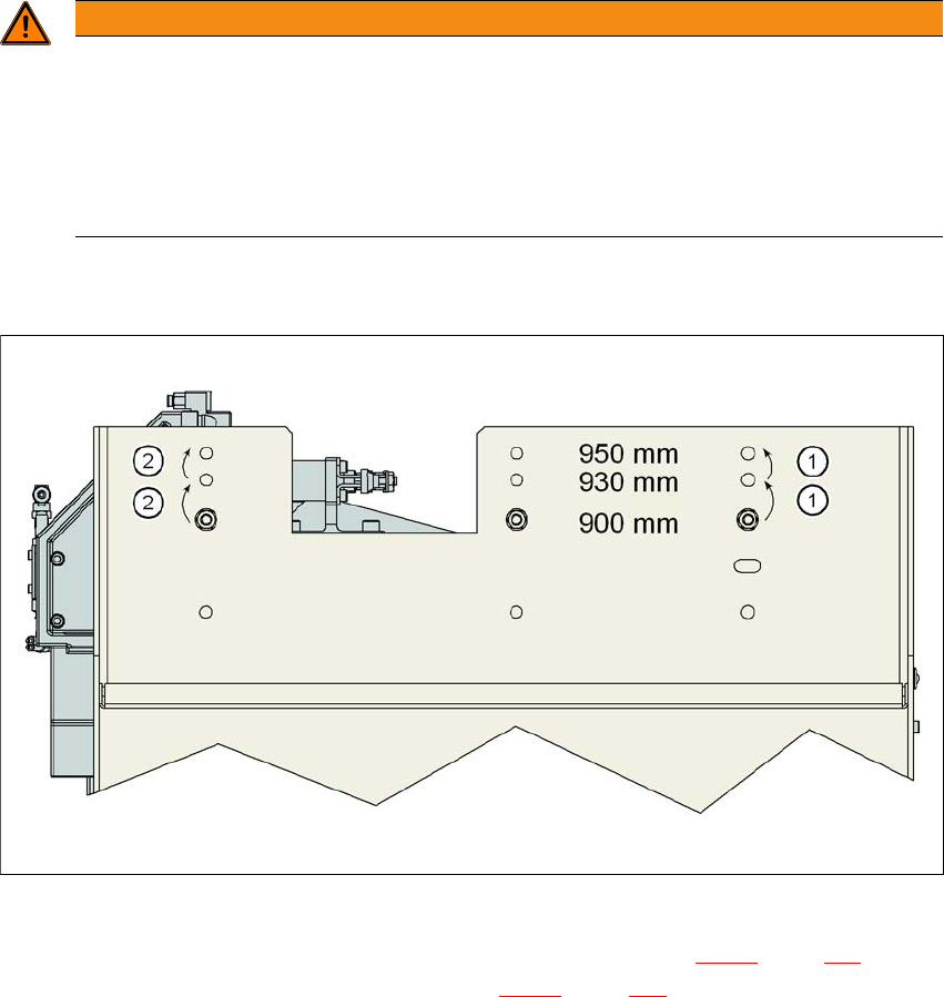
6.8.5.3 Converting the COT insert to heights of 900, 930 or 950 mm
6
Fig. 6.8 - 6 Order of conversion steps
Loosen the two hexagon socket-head screws M8x18 (item 9 in fig. 6.8 - 5, page 375) and re-
move the left and right guidance (item 8 in fig. 6.8 - 5
, page 375).
WARNING
Disconnect the docking station from the power supply.
Disconnect the docking station from the compressed air supply.
The weight of the COT insert is approx. 40 kg.
If required, enlist the help of a second person to help you with the conversion.
Follow the steps in the order described.