00197902-03_UM_X-Serie-S_EN.pdf - 第220页
4 Setting up and commissioning User manual SIPLACE X-Series 4.2 Infrastructure at the installation location From software versio n 710.0 Edition 12/2016 220 4.2.3.5 Connecting the power supply cable 4 Fig. 4.2 - 6 T ermi…
User manual SIPLACE X-Series 4 Setting up and commissioning
From software version 710.0 Edition 12/2016 4.2 Infrastructure at the installation location
219
4.2.3.4 Mains connection - delivery configuration
The main power connection is configured according to the power supply of the country concerned.
– The machine is configured for voltages of 3 x 200 V~ to 3 x 240 V~ ± 10 %; 50/60 Hz.
The machine has a mains power cable WITHOUT plug. 4
4
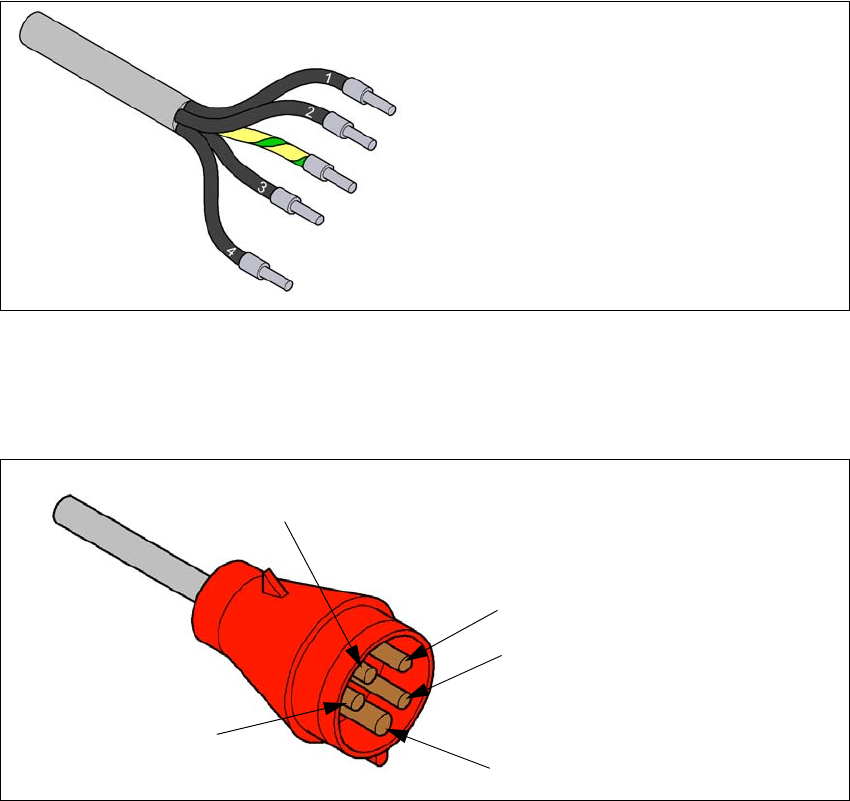
Fig. 4.2 - 4 Description of wires in the mains power cable
– The machine is configured for voltages of 3 x 360 V~ to 3 x 480 V ± 10 %, 50/60 Hz.
The machine has a mains power cable WITH Cekon plug. 4
4
Fig. 4.2 - 5 Assignment in the Cekon plug
1 = (L1): three-phase
2 = (L2): three-phase
3 = (L3): three-phase
4 = (N): neutral conductor
green/yellow = (PE): conductor
PE
L1
L2
L3
N
4 Setting up and commissioning User manual SIPLACE X-Series
4.2 Infrastructure at the installation location From software version 710.0 Edition 12/2016
220
4.2.3.5 Connecting the power supply cable
4
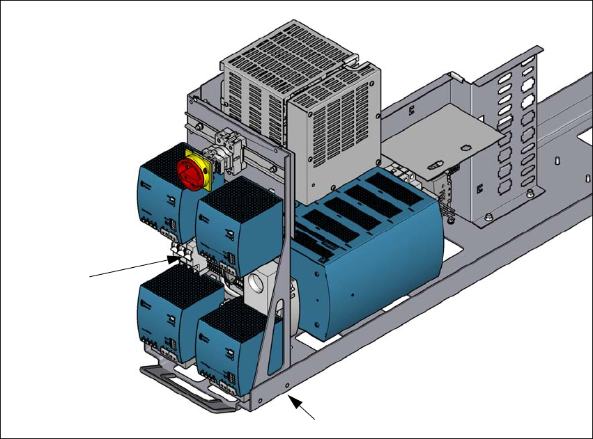
Fig. 4.2 - 6 Terminal panel for connecting the power cable
(1) Mains terminals (X95) for the power supply cable
(2) Opening on the power supply with cable fixture under the power supply
Crimp a ferrule onto each end of the wire.
Run the mains power cable through the cable fixture under the power supply (2) to the termi-
nal panel X95 (1).
Fasten the cable to the terminal panel X95 (1)
(L1): three-phase 4
(L2): three-phase 4
(L3): three-phase 4
(N): neutral conductor 4
(PE): PE conductor 4
Make sure that the bending radius is adequate. The wires must not be kinked.
Manually tighten the cable fixture.
Make sure you also fix the cable with cable ties.
(1)
(2)
User manual SIPLACE X-Series 4 Setting up and commissioning
From software version 710.0 Edition 12/2016 4.2 Infrastructure at the installation location
221
4.2.4 Overview of the microfuses
4
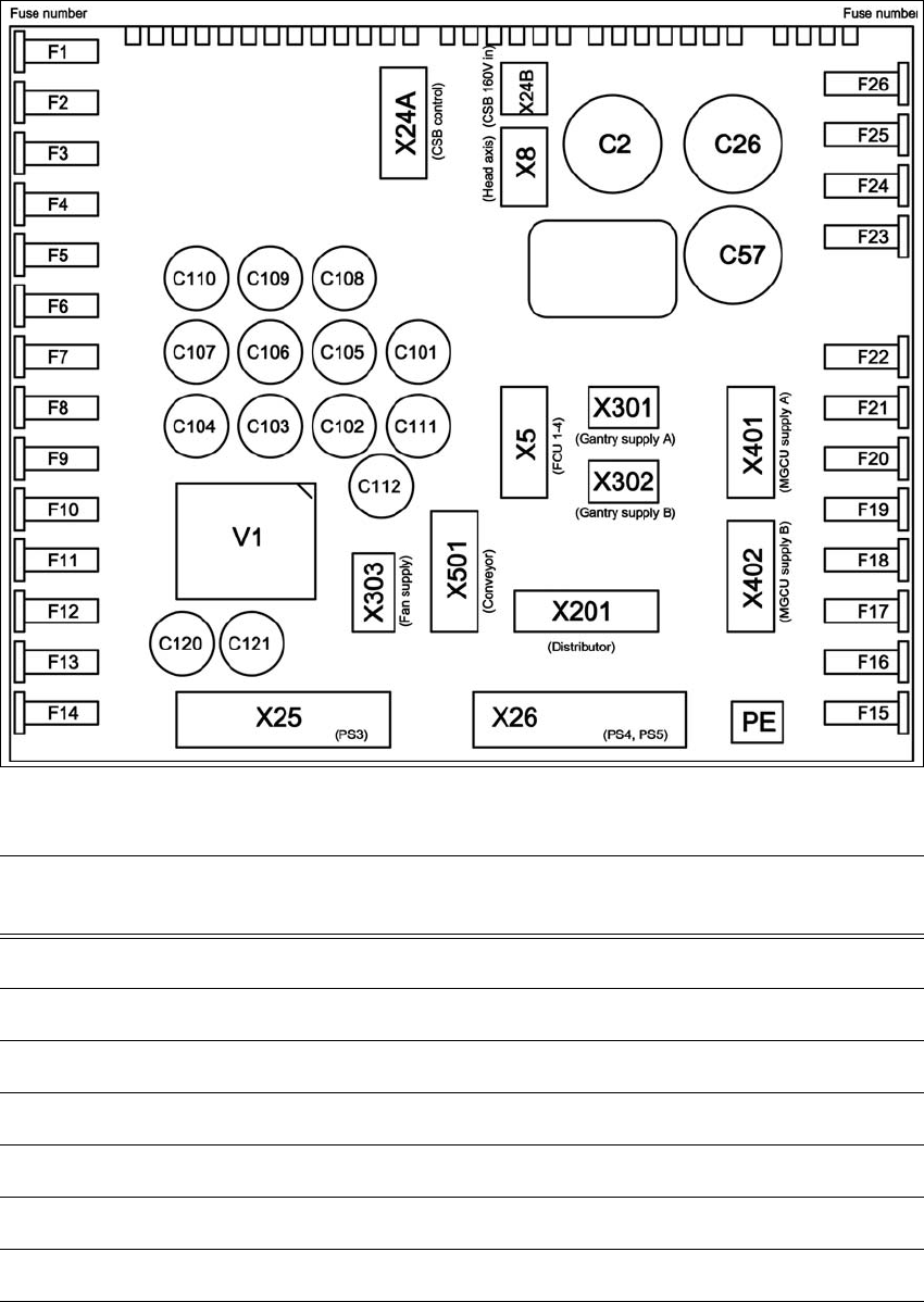
Fig. 4.2 - 7 Overview of the microfuses
4
Fuse Components Electricity
[A]
Voltage [V]
F1 CSB supply 6,3 24
F2 SSK-Ready CSB 6,3 24
F3 Conveyor control 6,3 24
F4 Distributor power 2 6,3 24
F5 Distributor power 1 6,3 24
F6 Fan gantry 1 / 4 6,3 24
F7 Fan gantry 2 / 3 6,3 24