00197902-03_UM_X-Serie-S_EN.pdf - 第386页
6 Station extensions User manual SIPLACE X-Series 6.12 Siemens interface From software version 710.0 Edition 12/2016 386 6.12 Siemens interface Item no. 001 16808-xx SIPLACE inte rface The conveyor interface on the place…
User manual SIPLACE X-Series 6 Station extensions
From software version 710.0 Edition 12/2016 6.11 Stationary cameras
385
6.11.2.1 Safety instructions
6
6.11.2.2 Technical data
6
6
WARNING
Risk of collisions!
When changing the placement head from a TwinStar/VHF to a SpeedStar, the SpeedStar
collides with the camera housing.
Dismantle the stationary component camera for the TwinStar.
When changing the placement head from a TwinStar to a MultiStar, the stationary
component camera is fitted in the bottom position.
Component dimensions 0.5 mm x 0.5 mm to 55 mm x 45 mm
Component range 0402, MELF, SO, PLCC, QFP, electrolytic capacitors, BGA
Min. lead pitch 0.3 mm
Min. lead width 0.15 mm
Min. ball pitch 0.35 mm
Min. ball diameter 0.2 mm
Field of vision 65 mm x 50 mm
Illumination type Front-illumination (6 levels, programmable as required)
6 Station extensions User manual SIPLACE X-Series
6.12 Siemens interface From software version 710.0 Edition 12/2016
386
6.12 Siemens interface
Item no. 00116808-xx SIPLACE interface
The conveyor interface on the placement machines from the X-Series is configured to the SMEMA
standard. It is, however, still possible to use this interface in accordance with the Siemens stan-
dard. This is a significant benefit when an X-Series machine is to be integrated into older SIPLACE
lines, in which case it would not be necessary to retrofit the older machines to conform to the
SMEMA standard.
Simply configure the conveyor interface of the X-Series machines to the Siemens standard and
connect the machines using the associated interface cable.
User manual SIPLACE X-Series 6 Station extensions
From software version 710.0 Edition 12/2016 6.13 Support pin
387
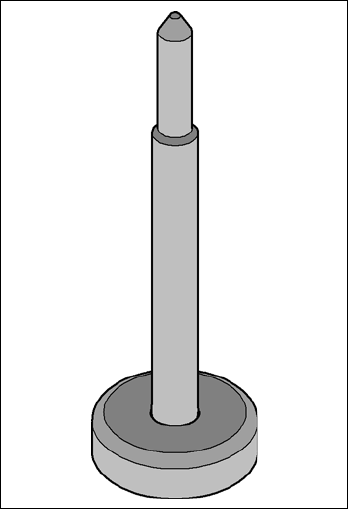
6.13 Support pin
Item no. 00119680-xx Support pin
Wide boards tend to deflect during placement such that, under certain circumstances, the compo-
nents can no longer be placed with the desired accuracy. Highly curved PCBs also affect the
placement accuracy. This problem can be easily rectified by fitting support pins on the lifting table.
6
Fig. 6.13 - 1 Support pin