00197902-03_UM_X-Serie-S_EN.pdf - 第381页
User manual SIPLACE X-Series 6 Station extensions From software version 710.0 Edition 12/2016 6.10 3D coplanarity laser module 381 6.10.2 T echnical data 6 Components QFP, SO, BGA, Gullwing, connector Accuracy *a ± 15 μ …

6 Station extensions User manual SIPLACE X-Series
6.10 3D coplanarity laser module From software version 710.0 Edition 12/2016
380
6
6
6
6
WARNING
Laser radiation is hazardous for the eyes
The accessible laser radiation is dangerous for your eyes and, in certain circumstances,
also poses a hazard to skin.
The radiation issued by class 3B lasers (medium output strength) is dangerous during
direct contact with your eyes and also when it is reflected by a mirror. At higher output
levels, this laser could also damage skin.
Avoid looking directly into the laser beam.
The 3D coplanarity module is installed and secured in the machine in a manner
which, if used correctly (short radiation periods), fulfills the laser class 2 limits for ac-
cessible radiation and is therefore non-hazardous for your eyes.
WARNING
Encapsulated class 2 laser equipment
When in a fixed installation, the placement machine is classified as a so-called "encap-
sulated" class 2 laser device
The 3D sensor is integrated into the emergency OFF circuit.
Never disable the emergency OFF circuit!
The 3D sensor may only be operated inside the placement machine!
WARNING
Repairs and service
For repair and service work, always send the sensors to ASM Assembly Systems
GmbH & Co. KG.

User manual SIPLACE X-Series 6 Station extensions
From software version 710.0 Edition 12/2016 6.10 3D coplanarity laser module
381
6.10.2 Technical data
6
Components QFP, SO, BGA, Gullwing, connector
Accuracy
*a
± 15 μm (3σ), ± 20 μm (4σ)
Maximum component size 50 x 50 mm²
Maximum component height 17 mm
BGA component shape
Min. ball diameter
Min. ball pitch
Min. number of balls
400 μm
800 μm
6
Gullwing component shape
Min. lead width
*b
Min. lead pitch
Min. number of leads
300 μm
500 μm
5
Maximum connector size 120 x 20 mm²
Connector (Gullwing)
Min. lead width
b
Min. lead pitch
Min. number of leads
300 μm
500 μm
5
Placement head type TwinHead, MultiStar
Laser protection class
3D coplanarity sensor
Placement machine
3B
2
*)a Per ball/lead
*)b Contact your local product manager for details of smaller lead widths
6 Station extensions User manual SIPLACE X-Series
6.11 Stationary cameras From software version 710.0 Edition 12/2016
382
6.11 Stationary cameras
6.11.1 Stationary P&P component camera (type 25) 16 x 16, digital (FC camera)
Item no. 03105205-xx Stationary component camera 16x16 digital, type 25
6
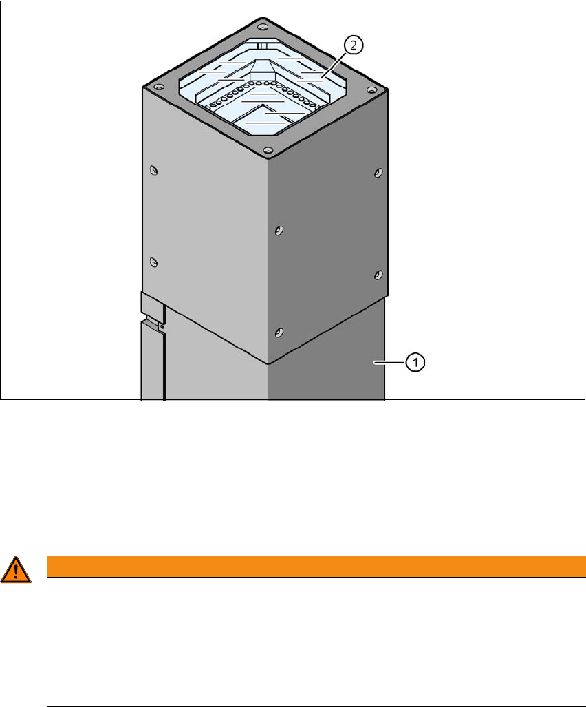
Fig. 6.11 - 1 Stationary P&P component camera (type 25) 16 x 16, digital (FC camera)
(1) Camera housing with integral camera and camera amplifier
(2) Glass plate - illumination and lens levels below
6.11.1.1 Safety instructions
6
WARNING
Risk of collisions!
When changing the placement head from a TwinStar/VHF to a SpeedStar, the SpeedStar
collides with the camera housing.
Dismantle the stationary component camera for the TwinStar.
When changing the placement head from a TwinStar to a MultiStar, the stationary
component camera is fitted in the bottom position.