00197902-03_UM_X-Serie-S_EN.pdf - 第378页
6 Station extensions User manual SIPLACE X-Series 6.9 SIPLACE High-Force Head From software version 710.0 Edition 12/2016 378 6.9 SIPLACE High-Force Head Item no. 001 1 9736-xx High-Force Head This item number only appli…
User manual SIPLACE X-Series 6 Station extensions
From software version 710.0 Edition 12/2016 6.8 Docking station for the component trolley of the SIPLACE X-Series
377
6
Unscrew the two screwed connections (item 3 in fig. 6.8 - 5, page 375).
Loosen the two other screwed connections (item 2 in fig. 6.8 - 5, page 375).
Remove the two M8 hexagonal nuts and washers (item 4 in fig. 6.8 - 5, page 375).
Hold the COT insert by its side (item 10 in fig. 6.8 - 5, page 375) and remove the two hexagon
socket-head screws M8x40 here.
Swivel the COT insert to the next highest position.
Fasten the side panel at this point. Tighten the nuts loosely to do this.
Hold the COT insert by the FCU (item 12 in fig. 6.8 - 5, page 375) and remove the screwed
connections at item 2 in fig. 6.8 - 5
, page 375.
Swivel the COT insert to the next highest position.
Fasten the side panel at this point.
Check that all screwed connections at items 2, 3 and 4 are tightened firmly.
Fasten the right and left guidances (item 8 in fig. 6.8 - 5, page 375) with the hexagon socket-
head screw M8x18 (item 9 in fig. 6.8 - 5
, page 375).
6
CAUTION
Risk of damage!
When raising and lowering the COT insert, cables can be damaged.
When raising and lowering the COT insert, make sure that no cables are damaged.
PLEASE NOTE
If you want to lower the COT insert to a different height, follow the above instructions
in reverse order.

6 Station extensions User manual SIPLACE X-Series
6.9 SIPLACE High-Force Head From software version 710.0 Edition 12/2016
378
6.9 SIPLACE High-Force Head
Item no. 00119736-xx High-Force Head
This item number only applies when ordering a new placement machine with a high force
head instead of a standard TwinStar. 6
6.9.1 Description
The SIPLACE high force head is an advanced development of the standard TwinStar. It can pro-
cess the same component range and also offers the possibility of achieving set-down forces up to
30 N. The SIPLACE high force head can use all the same nozzles and grippers as the standard
TwinStar.
6.9.2 Technical data
6
Al other technical data are identical for the TwinStar and high force head (see section 3.5.7.2,
page 155
).
Programmable set-down force 2.0 N to 10 N ± 10 %
greater than 10 N up to 30 N ± 15 %
User manual SIPLACE X-Series 6 Station extensions
From software version 710.0 Edition 12/2016 6.10 3D coplanarity laser module
379
6.10 3D coplanarity laser module
Item no. 519807-xx 3-D coplan, X2 S / X3 S / X4 S
The 3D coplanarity laser module works with a line of laser light. This enables you to generate and
analyze the height profile of a two-dimensional arrangement of component leads e.g. BGA, QFP
etc. This analysis provides data about the coplanarity (contact plane) and collinearity (contact line
straightness) of component leads or balls.
For more details, refer to the "Assembly Instructions 3D Sensor", German+English [Item. no.
00197084-xx]
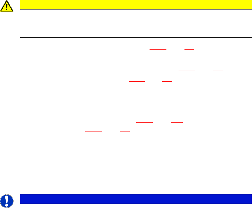
6.10.1 Safety instructions for coplanarity module sensor
The sensor works with a semiconductor laser which has a wave length of 670 nm (visible/red).
The maximum optical output is 60 mW.
The sensor is classified as laser class 3B.
– When using the sensor, always observe the IEC 60825-1:2014 regulations about "Safety of
Laser Equipment" and the accident prevention guidelines for "Laser Radiation" (DGUV Reg-
ulation 11), applicable in Germany.
– Also observe the accident prevention regulations of your own country!
The following warning labels are attached to the front and back of the sensor housing:
6
Fig. 6.10 - 1 Laser class 3B classification for the sensor