00197902-03_UM_X-Serie-S_EN.pdf - 第175页
User manual SIPLACE X-Series 3 Technical data and assemblies From software version 710.0 Edition 12/2016 3.8 X feeder modules for SIPLACE X-Series 175 3.8.1.3 Design of SIPLACE X feeder modules The following digram shows…

3 Technical data and assemblies User manual SIPLACE X-Series
3.8 X feeder modules for SIPLACE X-Series From software version 710.0 Edition 12/2016
174
3.8 X feeder modules for SIPLACE X-Series
The SIPLACE X-Series uses SIPLACE X feeder modules and the SIPLACE Smart Feeder X. The
specified feeder modules are compatible with the SIPLACE X-Series changeover tables. Key fea-
tures of the SIPLACE tape feeder modules include high pickup position precision, online program-
ming and simple handling of feeder module changeovers during the placement process. The
power supply to the feeder modules is contactless and uses an inductive interface. Each feeder
module communicates with the feeder module control unit (FCU) via two optoelectronic channels
(optical fiber). The two interfaces form the EDIF assembly (energy and data interface).
3.8.1 SIPLACE tape feeder module
3.8.1.1 Tape material
The possible tape widths range from 4 mm to 88 mm. The tape material is blister or paper. Com-
ponent tapes with a permanently adhesive cover foil (PSA foil) can also be processed.
The design of the tape feeder modules was based on the following tape standards:
DIN EN 60286-3 (12/1998) / IEC 60286-3 (12/1997)
JIS C 0806-3 (1999)
ANSI/EIA 481-C (10/2003)
IEC 60286-3-2 3
3.8.1.2 Manual removal of tantalum capacitors which were not picked up
To prevent tantalum capacitors which were not picked up from causing the tape material to burn
when it is cut, the user interface has been extended to include the option "Stop immediately on
pickup error". This option must be enabled in SIPLACE Pro. On the placement machine, the com-
ponent that was not picked up is paced forward again until it is ready for removal from the com-
ponent tape. The track is deactivated and the operator is sent an error message to remind him to
pick up the tantalum component from the tape. If an alternative track is available, the machine con-
tinues placing. The operator is able to stop the machine, however, and pick up the tantalum com-
ponent. If no alternative track is available and it is not possible to continue placement with other
components, the machine will stop. At this point, the operator can again remove the tantalum com-
ponent and acknowledge the error. Once the operator has restarted the machine, placement is
continued and components are picked up from the track that is now enabled once more.
3
PLEASE NOTE
This software function is also a good idea for expensive components.
Please observe the safety instructions for capacitors on metallic powder basis (see
section 2.5.3
, page 78).
User manual SIPLACE X-Series 3 Technical data and assemblies
From software version 710.0 Edition 12/2016 3.8 X feeder modules for SIPLACE X-Series
175
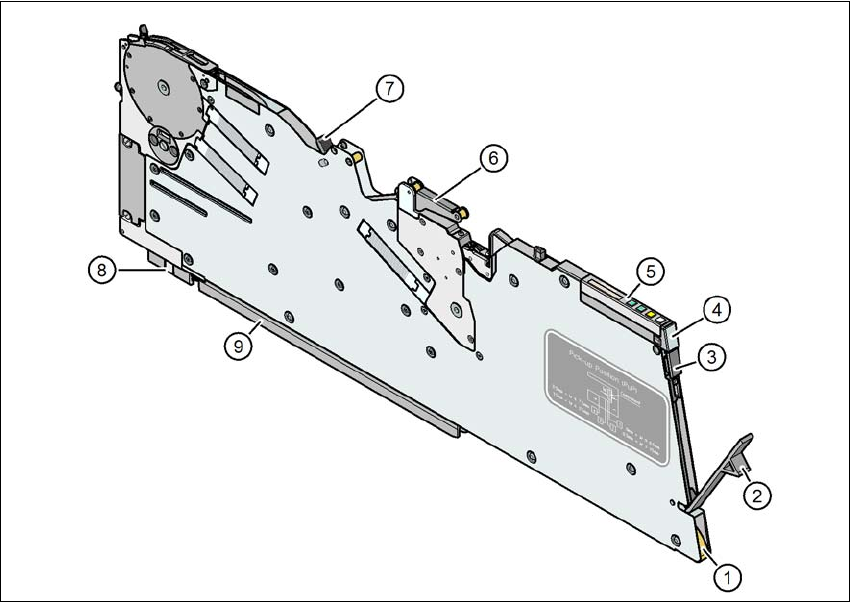
3.8.1.3 Design of SIPLACE X feeder modules
The following digram shows the design of the SIPLACE X feeder modules.
3
Fig. 3.8 - 1 SIPLACE X feeder module
(1) Entry to the tape guide channel with tape spring
(2) Flap on cover foil container
(3) Removal handle, engaged
(4) Status display
(5) Operating panel - LCD display
(6) Foil rocker
(7) Tape guide channel outlet
(8) Front slider guide
(9) Back slider guide
3 Technical data and assemblies User manual SIPLACE X-Series
3.8 X feeder modules for SIPLACE X-Series From software version 710.0 Edition 12/2016
176
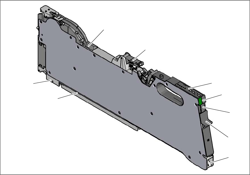
3.8.1.4 SIPLACE Smart Feeder design
The following digram shows the design of the SIPLACE Smart Feeder.
3
Fig. 3.8 - 2 SIPLACE SMART Feeder
(1) Entry to the tape guide channel with tape spring
(2) Flap on cover foil container
(3) Removal handle, engaged
(4) Status display
(5) Operating panel - LED display
(6) Foil rocker
(7) Tape guide channel outlet
(8) Front slider guide
(9) Back slider guide
(1)
(2)
(3)
(4)
(5)
(6)
(8)
(9)
(7)