00197902-03_UM_X-Serie-S_EN.pdf - 第30页
1 Introduction User manual SIPLACE X-Series 1.2 Machine description From software version 710.0 Edition 12/2016 30 1.2 Machine description 1.2.1 The SIPLAC E principle The placement heads pick up the co mponent s from th…

User manual SIPLACE X-Series 1 Introduction
From software version 710.0 Edition 12/2016 1.1 Machine overview
29
Three placement methods are possible for processing the components:
– Collect&Place,
– Pick&Place and
– A combination of Collect&Place and Pick&Place (mixed mode).
The SIPLACE X2 S placement machine has two placement areas, one single conveyor or one
dual conveyor. Two boards can be placed at the same time on dual conveyors.
There are four locations available for supplying components. These can be fitted with component
trolleys and configured with up to 40 tracks.
The SIPLACE X2 S placement machine has two gantries. The gantry in placement area 1 points
to location 4. The gantry in placement area 2 points to location 2.
These can be quickly and accurately positioned by linear motors, moving independently of one
another in the X and Y directions.
1.1.6.1 Overview of placement head configuration
1
CPP_H = Multistar CPP in high assembly position
CPP_L = Multistar CPP in low assembly position
Placement area 1 Placement area 2
C&P20 C&P20
C&P20 CPP_L
C&P20 CPP_H
CPP_L CPP_L
CPP_H CPP_H
CPP_L CPP_H
C&P20 TH
CPP_L TH
CPP_H TH
TH TH
1 Introduction User manual SIPLACE X-Series
1.2 Machine description From software version 710.0 Edition 12/2016
30
1.2 Machine description
1.2.1 The SIPLACE principle
The placement heads pick up the components from the fixed feeder modules on the component
trolley and then place the waiting boards.
The principle of "stationary component supply" and "stationary PCB", which have proven them-
selves in the other SIPLACE machines, offer a range of decisive benefits:
– Refilling components and splicing on tapes does not cause downtime.
– The vibration-free component feeder means that even the smallest components (e.g. 03015)
are picked up reliably.
– The PCB, which does not move during the placement process, prevents the components slip-
ping.
– The combination of placement heads with nozzle changers always guarantees an optimum
nozzle configuration for every placement process, thus minimizing traversing paths and opti-
mizing the placement sequence.
High flexibility, efficiency and reliable setups are the guarantee for top productivity in the SIPLACE
machines.
Minimum down times increase utilization and thus help to increase productivity.
User manual SIPLACE X-Series 1 Introduction
From software version 710.0 Edition 12/2016 1.2 Machine description
31
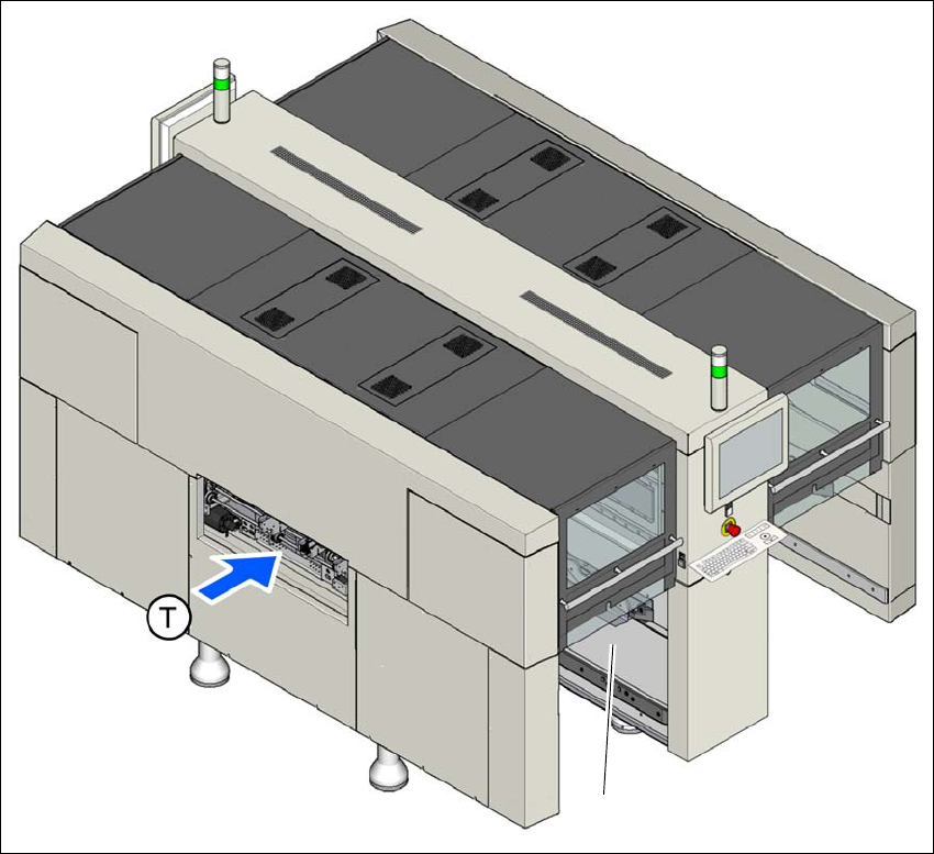
1.2.2 Machine serial number
The serial number of the machine can be found on the inside of the machine frame at location 1.
1
Fig. 1.2 - 1 Position of typeplate with serial number (example of SIPLACE X2 S / X3 S / X4 S machine shown)
(T) Direction of travel
(1) Typeplate
(1)