80S-15贴片机.pdf - 第109页
SIPLACE 80 S/ F/G Service M anual 4 Power S upply Edition 04/97 4 - 13 4.3 Control Unit 4.3.1 General The co ntrol uni t is locate d at the back of th e SIPLAC E mac hine in th e mach ine ba se (see Fig. 4.1 .1). ● Open …

4 Power Supply SIPLACE 80 S/F/G Service Manual
Edition 04/97
4 - 12

SIPLACE 80 S/F/G Service Manual 4 Power Supply
Edition 04/97
4 - 13
4.3 Control Unit
4.3.1 General
The control unit is located at the back of the SIPLACE machine in the machine base (see Fig. 4.1.1).
●
Open the metal door of the control unit.
●
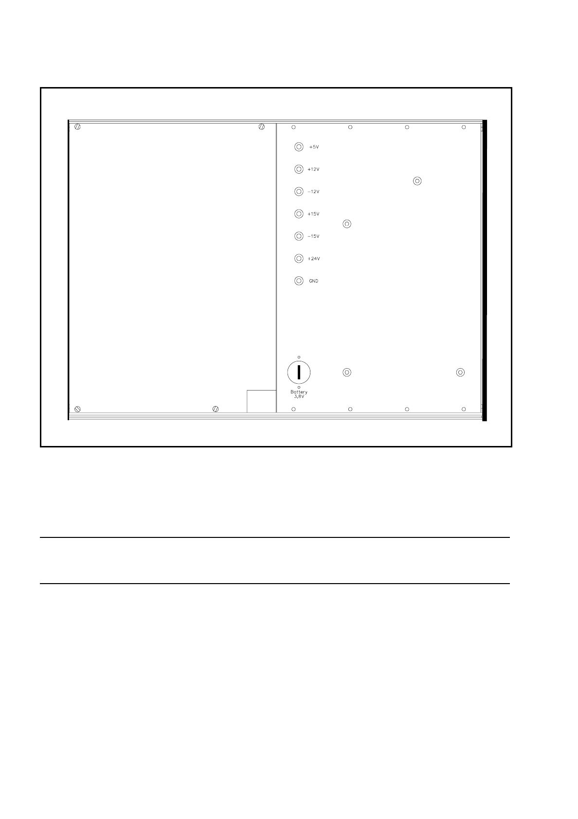
In the top part of the control unit you will find power supply unit A26 with the associated voltage measure-
ment sockets (see Fig. 4.3.1).
4.3.2 Supply Voltages
●
Switch the main switch of the machine on.
Power supply unit A26 supplies these direct voltages: + 5 V, + 12 V, – 12 V, + 15 V, – 15 V and 24 V.
●
At the voltage measurement sockets measure the direct voltages listed here (see Fig. 4.3.1).
Fuse F1 is located in power supply unit A26 and protects against overload the 5 V voltage supply which is
routed to the gantries via the ribbon cable.
F1 is a 3.15 A fuse. Use the digital ohmmeter to check whether the fuse is okay.
NOTE
If automatic circuit-breaker F1 is defective this may result in faults in the limit switch loops (limit switch acti-
vated). When making detailed measurements or carrying out fault location in the terminal rails or circuits you
should refer to the relevant circuit diagrams.
4 Power Supply SIPLACE 80 S/F/G Service Manual
Edition 04/97
4 - 14
Fig. 4.3.1 Control unit - partial view of the front with power supply unit
To make measurements at the back of the control unit proceed as follows:
●
Switch the placement machine off and disconnect it from the power supply.
●
Undo the retaining screw of the control unit and pull out the control unit.
CAUTION
Q
Make sure you do not damage the cable or put tensile stress on the snap-in connections.
●
If necessary, support the control unit on a stool.
●
Reconnect the machine to the power supply. Switch it on and then carry out the measurements required
(see Fig. 4.3.2). You should comply with the safety instructions in Section 1.