80S-15贴片机.pdf - 第353页
SIPLACE 80S/F/G Service Manual 9 Revolver Head Edition 04/97 9 - 69 9.7 Mechan ical Cent ering Station The mec hanical c enterin g stati on is l ocated i n revolv er head statio n 6 on the rear s ide o f the enc oder hou…

9 Revolver Head SIPLACE 80S/F/G Service Manual
Edition 04/97
9 - 68

SIPLACE 80S/F/G Service Manual 9 Revolver Head
Edition 04/97
9 - 69
9.7 Mechanical Centering Station
The mechanical centering station is located in revolver head station 6 on the rear side of the encoder housing.
It performs the following duties:
–
It centers components which cannot be optically centered in revolver head station 8. It aligns the center
point of the component with the nozzle center.
–
When the CRDL testing option is installed, it checks the electrical values of the components to see
whether they agree with those specified by the placement program.
Here the components which are to be centered and checked will first be rotated by turning station dp1 into the
correct position. If rotational errors have occurred at dp1, the centering station will not be activated. The com-
ponent is added to the "Not done" list and then blown off at revolver head station 3 into the rejects container.
Components lying with incorrect polarity are tested and then rotated by turning station dp2 into the correct
position.
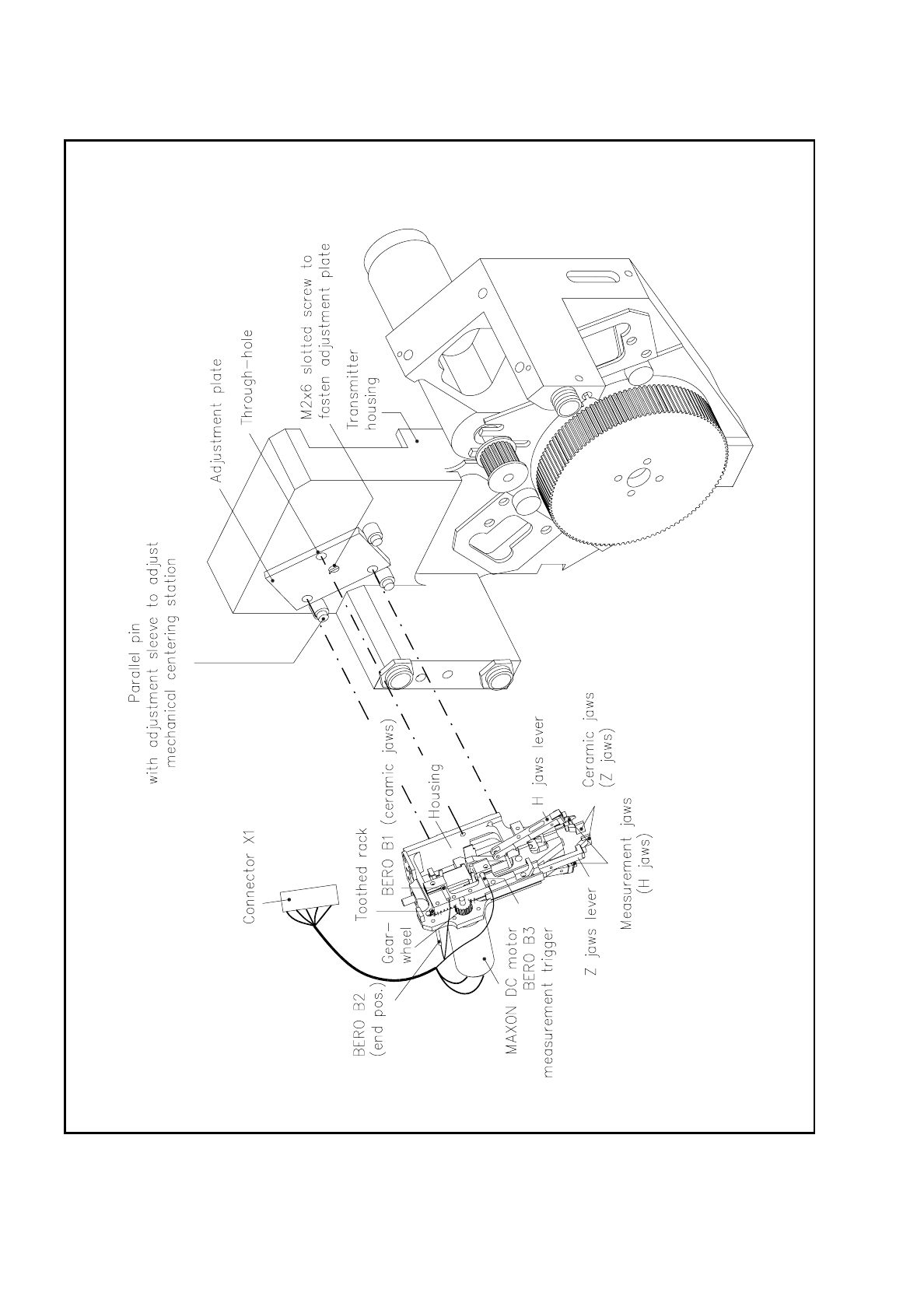
9.7.1 Installation and Alignment of the Mechanical Centering Station
The mechanical centering station is aligned in the factory with the center point of the revolver head by means
of three parallel pins and adjustment sleeves, with the corresponding clearance being also set. This means
that you will not need to carry out repeated alignment work after performing necessary servicing work, such as
changing jaw pairs and so on.
The mechanical centering station is fastened from the encoder housing side with three hexagon socket-head
screws to the encoder housing. The centering jaw midpoint is aligned with the nozzle center point of the seg-
ment with the aid of the adjustment plate (see Fig. 9.7.3).
NOTE
During maintenance or servicing work on no account remove the adjustment plate or the centering pins with
the adjustment sleeves. If this is done, the module will have to be reset in the factory.
9 Revolver Head SIPLACE 80S/F/G Service Manual
Edition 04/97
9 - 70
Fig. 9.7.1 Mechanical centering station