80S-15贴片机.pdf - 第346页
9 Revolver Head SIPLACE 80S/F/G Service Manual Edition 04/97 9 - 62 9.6.7 Conversion Board "H ead" 1710491-Y0 303 Fig. 9.6.14 Conver sion board “H ead“ - 1710491-Y0303
SIPLACE 80S/F/G Service Manual 9 Revolver Head
Edition 04/97
9 - 61
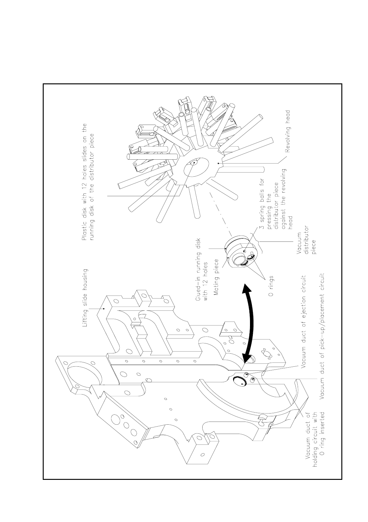
The glued-on running disk has 12 holes for the vacuum ducts. The additional depressions create a maximum
overlapping between the vacuum ducts of the running disk and the plastic slip disk in the revolver head so that
when the revolver head turns there can be no loss of vacuum in the individual vacuum circuits.
Fig. 9.6.13 Vacuum distributor piece
9 Revolver Head SIPLACE 80S/F/G Service Manual
Edition 04/97
9 - 62
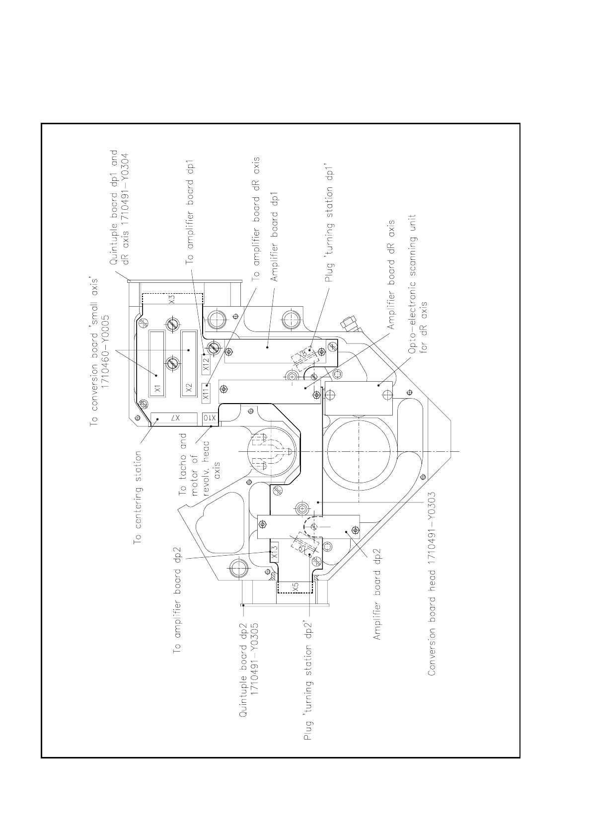
9.6.7 Conversion Board "Head" 1710491-Y0303
Fig. 9.6.14 Conversion board “Head“ - 1710491-Y0303

SIPLACE 80S/F/G Service Manual 9 Revolver Head
Edition 04/97
9 - 63
The conversion board "Head" 1710491-Y0303 is the central board in the revolver head. It carries all plug con-
nections for the individual function groups of the revolver head and is connected via plugs X1 and X2 with the
conversion board "Small axis" 1710460-Y0005. These connections run on to the conversion board "Gantry"
1710460-Y0003 and from there to the control and servo unit. The amplifier boards of the dp1, dp2 and dR
axes are also mounted on the conversion board "Head".
The following connections are made via the plugs on the conversion board "Head":
Plug X1 (26-pin) bero dp1
bero dp2
feed motor dp1
feed motor dp2
motor-tacho combination dp1 axis
motor-tacho combination dp2 axis
motor-tacho combination dR axis
voltage supply ± 5 V, 24 V
Plug X2 (26-pin) track signals A, A
, B, B and
zero pulse signals N, N
of the dp1, dp2 and dR axes
beros 1, 2 and 3 and
motor of the centering station
X3 (26-pin) quintuple board 1710491-Y0304 for conversion of the dp1 and dR axes analog track
signals to digital signals
board power supply
X5 (14-pin) quintuple board 1710491-Y0305 for conversion of the dp2 axis analog track signals to
digital signals
board power supply
X7 (11-pin) signals of beros 1, 2 and 3
motor of the centering stations
X8 (10-pin) bero dp1, feed motor
motor-tacho combination dp1
X9 (10-pin) bero dp2, feed motor
motor-tacho combination dp2
X10 (4-pin) motor-tacho combination dR axis
X11 (8-pin) track signal, zero pulse and power supply for the amplifier board of the dR axis
X12 (8-pin) track signals, zero pulse and power supply for the amplifier board of the dp1 axis
X13 (8-pin) track signals, zero pulse and power supply for the amplifier board of the dp2 axis