80S-15贴片机.pdf - 第343页
SIPLACE 80S/F/G Service Manual 9 Revolver Head Edition 04/97 9 - 59 A furthe r duty of the revo lver he ad is dis tributi on of vac uum to the s egmen ts on t he indiv idual va cuum circui ts: – Pick-up and plac ement ci…
9 Revolver Head SIPLACE 80S/F/G Service Manual
Edition 04/97
9 - 58
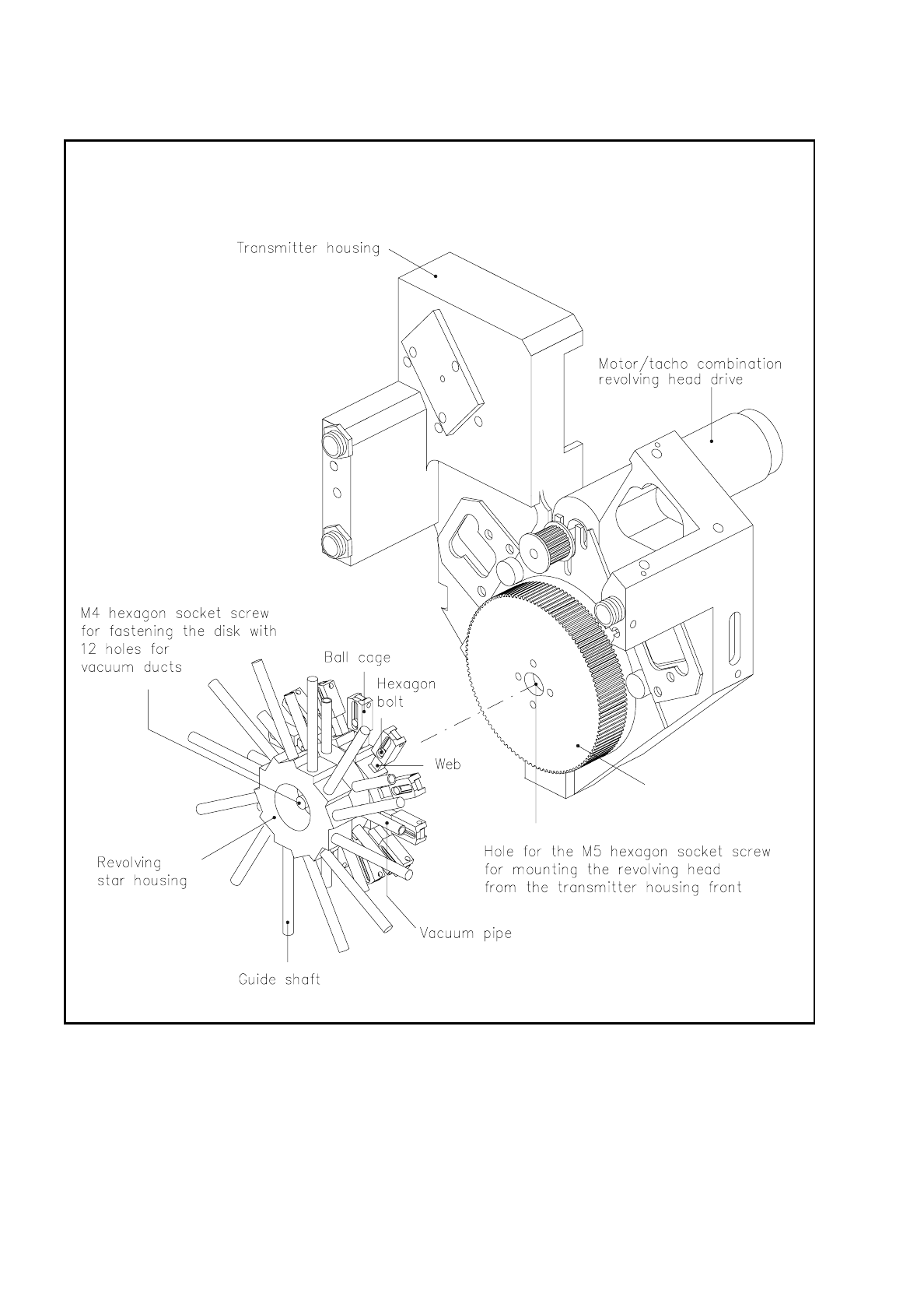
Fig. 9.6.11 Revolver head
SIPLACE 80S/F/G Service Manual 9 Revolver Head
Edition 04/97
9 - 59
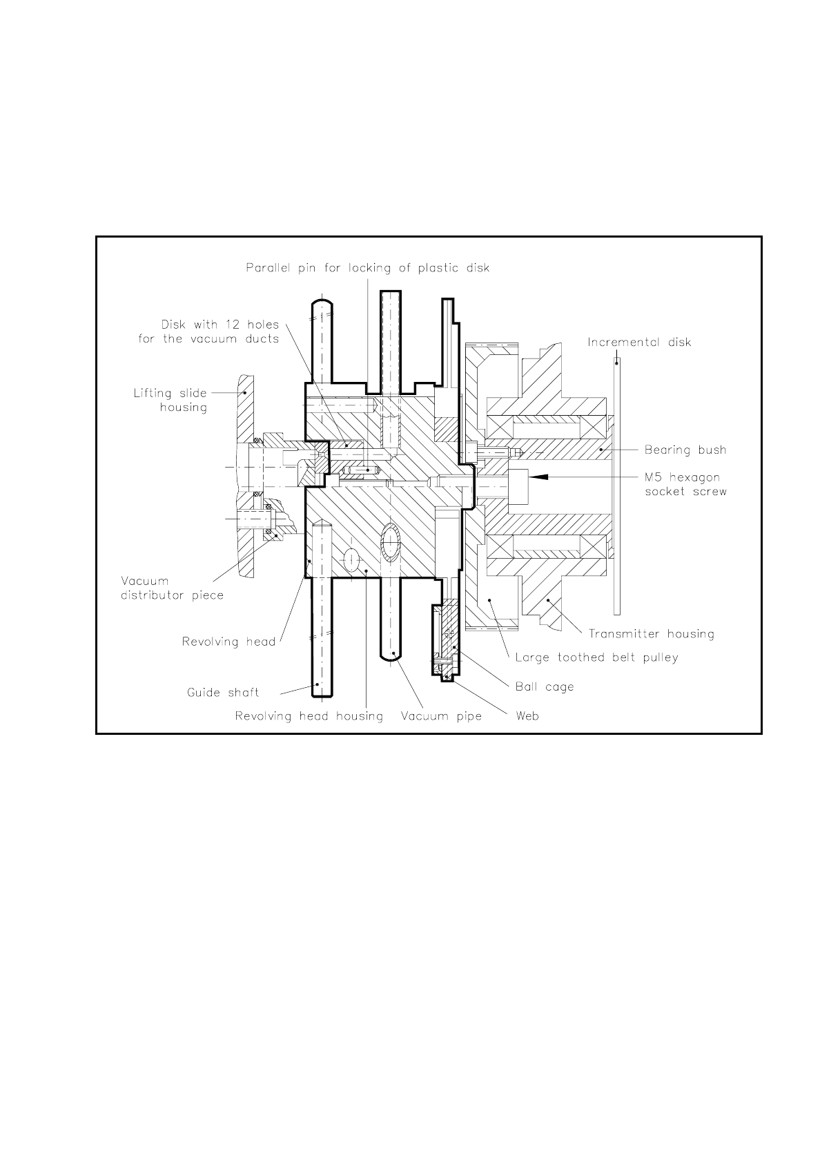
A further duty of the revolver head is distribution of vacuum to the segments on the individual vacuum
circuits:
–
Pick-up and placement circuit in revolver head station 1
–
Ejection circuit in revolver head station 3 and
–
Holding circuit with revolver head stations 2, and 4 to 12
Fig. 9.6.12 Installation of the revolver head with connections to the vacuum distributor piece
The revolver head basically consists of the following components:
–
Revolver head housing
–
12 guide shafts
–
12 vacuum pipes
–
12 webs with ball cages
–
Plastic disk with 12 holes for the vacuum ducts
The collar of the revolver head fits into the hole of the large toothed belt pulley and is connected from the
encoder housing front by an M5 hexagon socket-head screw with bearing bushing of the rotational drive.

9 Revolver Head SIPLACE 80S/F/G Service Manual
Edition 04/97
9 - 60
The 12 guide shafts and the ball cages running on the webs have the function of guiding the segments. The
individual segments are evacuated via the vacuum ducts.
The 12 guide shafts are let into blind holes in the revolver head housing.
The 12 vacuum tubes are also let into holes in the revolver head housing. From the side facing the lifting slide
housing 12 holes intersect with the vacuum tubes holes and form the 12 vacuum ducts. A disk centered with
two parallel pins and which has 12 holes for the vacuum ducts runs on the vacuum distributor coupling in
order that the vacuum is constantly maintained at the individual circuits.
The 12 webs are fastened in each case with two M1.4 fillister head screws to the revolver head housing. The
ball cages slide along the webs. In each guide strip there is a hexagon bolt which engages with the cage slot
and thus restricts the movement of the cage (see Fig. 9.6.11).
NOTE
The revolver head can only be removed or fitted in the factory.
9.6.6 Vacuum Distributor Piece
The vacuum distributor piece connects the three vacuum ducts in the lifting slide housing with the vacuum
circuits of the revolver head. There are a total of three vacuum circuits:
–
Holding circuit
The holding circuit includes revolver head stations 2 and 4 - 12. During the revolver head cycle the
vacuum is maintained in the individual segments. Pick-up components are held by underpressure to the
nozzle.
–
Pick-up and placement circuit
In revolver head station 1, components are sucked up by underpressure and blown off for placement.
–
Ejection circuit
In revolver head station 3
●
a defective component is ejected;
●
during the pick-up cycle the component shape "Good or bad nozzle contact" is tested;
●
the degree of nozzle contamination is checked;
●
the segment is checked for leaks.
The vacuum distributor piece consists of the following components (see Fig. 9.6.13):
–
mating piece
–
running disk, glued vacuum-tight to the mating piece
–
1 o-ring 9 x 1
–
1 o-ring 4 x 1.2 in each case for pick-up and placement circuit and for ejection circuit