80S-15贴片机.pdf - 第329页
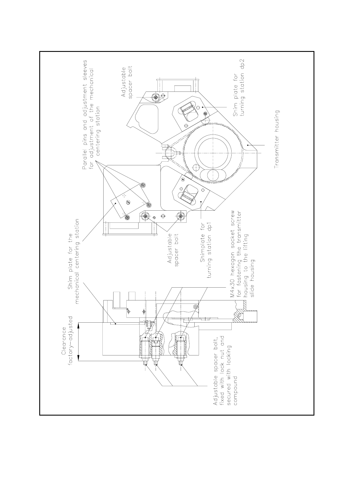
SIPLACE 80S/F/G Service Manual 9 Revolver Head Edition 04/97 9 - 45 Fig. 9. 6.2 Adjustment of the encoder ho using at the lifting slide housing

9 Revolver Head SIPLACE 80S/F/G Service Manual
Edition 04/97
9 - 44
The encoder housing "complete" with revolver head is centered on the lifting slide housing by means of two
parallel pins and fastened to it by three M4 hexagon socket-head screws.
The clearance of the encoder housing from the lifting slide housing is precisely set in the factory by means of
three spacer bolts (see Fig. 9.6.2). After adjustment is completed in the factory, the setting of the spacer bolts
is fixed with locknuts to which yellow locking compound is then applied. For this reason you can replace the
encoder housing or the revolver head at any time without additional mechanical setting work.
NOTE
Never undo the locknuts of the spacer bolts or you will have to have the clearance between the encoder hous-
ing and the lifting slide housing realigned in the factory.
SIPLACE 80S/F/G Service Manual 9 Revolver Head
Edition 04/97
9 - 45
Fig. 9.6.2 Adjustment of the encoder housing at the lifting slide housing
9 Revolver Head SIPLACE 80S/F/G Service Manual
Edition 04/97
9 - 46
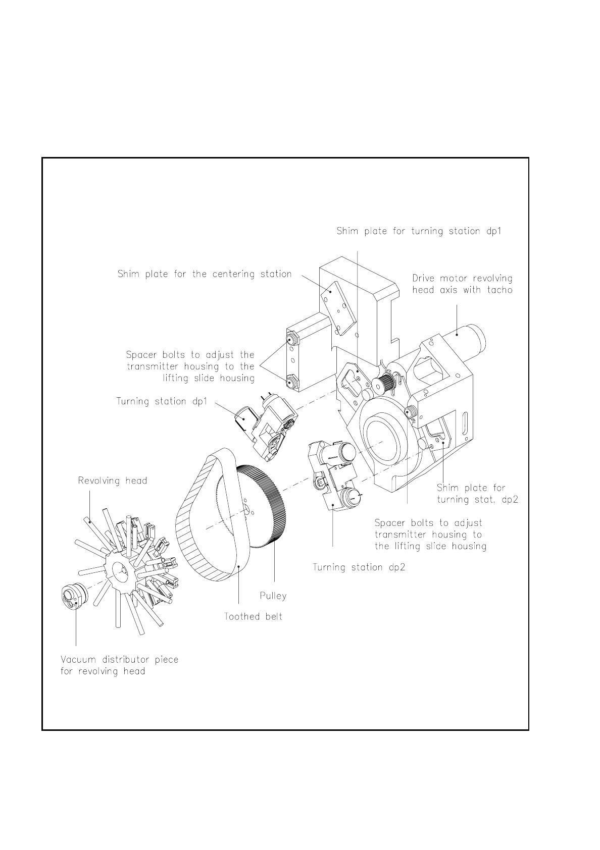
9.6.1 Module Overview of Encoder Housing "Complete" with Revolver
Head
Fig. 9.6.3 and Fig. 9.6.4 show the modules of the encoder housing "complete" with revolver head.
Fig. 9.6.3 Assemblies of the encoder housing “complete“ - rear view