80S-15贴片机.pdf - 第201页
SIPLACE 80 S/ F/G Service M anual 7 Components Table Edition 04/97 7 - 19 7.4 Fl ap Op ener (M agazi ne Op ener s) 7.4.1 Tools and Spare Parts Required Tools ● Screwdr iver fo r socket -head cap screws, s et ● Open-ende …
7 Components Table SIPLACE 80 S/F/G Service Manual
Edition 04/97
7 - 18
●
Slide the placement head by hand over the board conveyor (see CAUTION note in section 7.2 „Fault Char-
acteristics“ on page 7 - 11).
●
Release the clamping lever and lift and using a lift truck move the components changeover table including
fitted feeder modules carefully out of the machine as described in the User’s Manual.
●
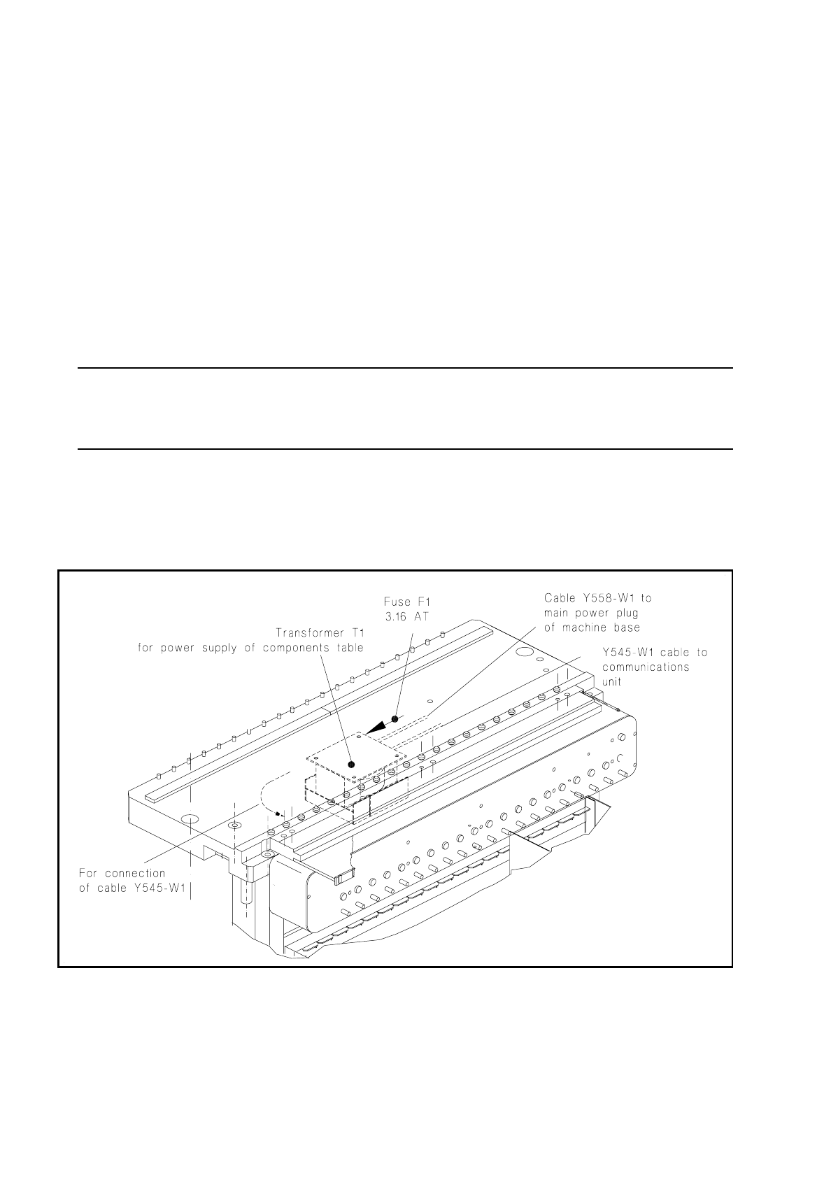
Unscrew and remove the fuse F1 at the transformer T1 (see Fig. 7.3.1).
–
If the fuse is defective, first, where possible, remove the cause of the problem, which should be looked
for on the output side of the transformer:
If necessary, remove the communications unit (see section 7.5 "Communications Unit") and use the
meter at the 5-pin plug (cable of power supply communications unit) to see whether there is a short
circuit in the cable or in the transformer winding. Please observe the following NOTE!
–
If you can correct the short circuit in another way, replace the 3.16 AT fuse.
NOTE
The transformer T1 and / or the cables Y558-W1 and Y545-W1 at the transformer (see Fig. 7.3.1) will be
replaced only by the SMD Service department of Siemens AG.
●
Install the components changeover table back in the machine in the reverse sequence of operations to
removal as described above. Make sure the plug connections (mains plug and X37, and, if applicable,
pneumatic connection) are firmly seated.
●
Switch the machine on and start the placement sequence.
Fig. 7.3.1 Components table power supply: checking and replacing the fuse

SIPLACE 80 S/F/G Service Manual 7 Components Table
Edition 04/97
7 - 19
7.4 Flap Opener (Magazine Openers)
7.4.1 Tools and Spare Parts Required
Tools
●
Screwdriver for socket-head cap screws, set
●
Open-ended spanner SW 7 (for screw-in cylinder)
●
Side-cutting pliers
Auxiliary Measuring and Test Equipment
●
Multimeter, range of measurement 30 VDC
●
Gauge blocks (dimension required: 285.5
±
0.2 mm)
Spare Parts
●
Flap opener SIPLACE 80, from Item No. 00116003-04
●
Adhesive tape
●
Compressed air hose
●
Cable lacing
7.4.2 Fault Location and Correction
NOTE
Error message No. 43 can indicate a fault in the flap opener.
Start fault location by referring to the section 7.2 "Fault Characteristics".
Information on the structure and functioning of the flap opener will be found in the section 7.1 "Overview".
If an individual flap opener is not being activated, the plunger will no longer extend or retract far enough or the
flap openers of an entire location (1 or 3) will not operate, proceed as described below.
7.4.2.1 Checking the Compressed Air Branch and Plug Connections
●
Select "Abort placement" in order to return all of the components picked up at the placement heads in the
course of the following reference run.

7 Components Table SIPLACE 80 S/F/G Service Manual
Edition 04/97
7 - 20
●
Remove the cover plate over the compressed air unit from the machine base (2 special socket-head cap
screws M3) and check the pressure for the flap opener on the lefthand pressure gauge of the compressed
air unit: it must show 2.8 bar.
–
If it does not, correct the pressure at the corresponding setting knob of the compressed air unit (for
setting, see User’s Manual, Section 9).
–
If the pressure was set correctly, proceed as follows:
DANGER
QQQ
Switch off the machine at the main switch and disconnect it from the power supply.
●
Open the protective cover.
●
Tighten up the threaded hose connections at the flap opener (see Fig. 7.4.1) and at the com-
pressed air unit. Make sure that the compressed air hose is not pinched or damaged.
●
If the compressed air hose has to be replaced,
switch off the machine at the main switch and
disconnect it from the power supply.
●
Switch off the compressed air at the shut-off valve of the compressed air unit (see User’s Manual,
Section 9) and replace the compressed air hose. Replace all cable lacings in their previous posi-
tion. Fit the cover plate back over the compressed air unit.
●
Please note: The compressed air hose at the flap opener connection must be routed between the
machine base and the clamping lever in order to keep it clear of the cutter wheel.
●
Make sure the plug connection X38 at the "Flap opener control" board is firmly seated and con-
tacting properly (position: on the left below the strip, see Fig. 7.4.2).
●
Continue work with the next section.
7.4.2.2 Checking Functioning and Continuing Fault Location
DANGER
OOO
The SITEST program must only be used by
authorized personnel who have been specially trained
in this
at Siemens AG (please observe the DANGER notes in section 7.6.2 on page 7 - 34).
●
Switch the machine on and load the SITEST program.
●
Select from within the SITEST main menu "Functions"
→
"BE table"
→
"Continuous loop CL"
→
"Magazine
opener". All of the flap openers of a location will activated one after the other.
●
Check whether the entire flap opener is not being activated or possibly only an individual plunger is not
extending or retracting. Finish continuous operation by selecting "finish":
●
If the flap openers of an entire location are not being activated, first check with "Continuous loop CL" acti-
vation in the opposite location.
●
If the flap openers of both locations (1 and 3) are not being activated, proceed as follows: