80S-15贴片机.pdf - 第363页
SIPLACE 80S/F/G Service Manual 9 Revolver Head Edition 04/97 9 - 79 9.8 Segments The revo lver he ad has a total of 1 2 segm ents. Th e segment s slide on the guide sha fts of t he revolve r head. Evacua tion of the segm…

9 Revolver Head SIPLACE 80S/F/G Service Manual
Edition 04/97
9 - 78
The centering station motor is activated via the S5 outputs
Port A5.4 } for the gantry 1) with 80S machines
Port A9.4 } for the gantry 2) with 80S machines
Port A5.4 } with 80F machines
The end signal is present at the following inputs of the S5 controller
Port E5.4 } for the gantry 1) with 80S machines
Port E9.4 } for the gantry 2) with 80S machines
Port E5.7 } with 80F machines
9.7.4.1 Centering with Measurement
–
The motor controller is set via the output Port A5.4 or A9.4.
–
The toothed strip support moves with the claws towards the segment. The pairs of jaws close. As soon as
both pairs of jaws have closed, the measurement triggering bero B3 is released.
–
After a short delay to avoid bounce effects the measurement procedure starts.
–
Measurement takes about 30 ms.
–
Once measurement is finished, the motor controller is reset. The toothed strip support moves towards the
rest position. The jaws then open.
–
Once the rest position is reached, the end position bero B2 is activated. The centering station is held in its
rest position by the quiescent current of approx. 200 mA.
–
After this centering procedure is completed the end signal will be given; the revolver head can cycle on.
9.7.4.2 Centering without Measuring
–
The motor controller is set via the output Port A5.4 or A9.4.
–
The toothed strip support moves with the claws towards the segment. The jaw pairs begin to close.
–
When the z jaws (ceramic jaws) touch the component, the ceramic jaws bero B1 is released
(Ports E5.5 or E9.5).
–
The motor current is increased and the h jaws (measuring jaws) close more rapidly.
–
Once the h jaws have also closed, the measurement triggering bero B3 is released (Ports E5.7 or E9.7).
–
The motor controller is reset. The toothed strip support moves towards the rest position. The jaws then
open.
–
Once the rest position is reached, the end position bero B2 is activated. The centering station is held in its
rest position by the quiescent current of approx. 200 mA.
–
After this centering procedure is completed the end signal will be given; the revolver head can cycle on.

SIPLACE 80S/F/G Service Manual 9 Revolver Head
Edition 04/97
9 - 79
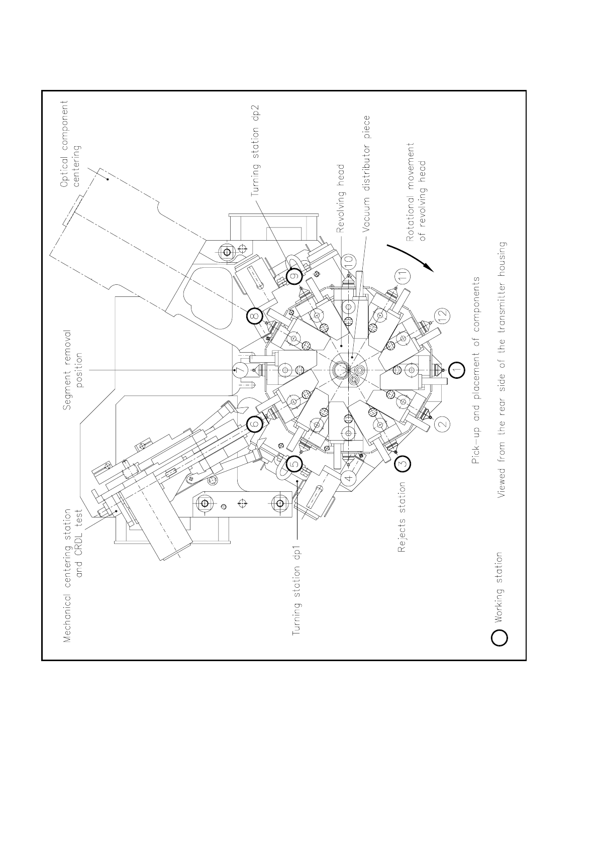
9.8 Segments
The revolver head has a total of 12 segments. The segments slide on the guide shafts of the revolver head.
Evacuation of the segment or nozzle takes place via the vacuum tube of the revolver head.
As the revolver head cycles on, the segments bring the picked-up components to the individual work stations
of the revolver head. At each work station the actions required for mounting the components will be
performed. The following revolver head stations are work stations:
At revolver head station 7 you can remove and fit segments using the segment removal tool.
Revolver head station Work performed
1 Pick-up and placement of components
3 Ejection of components
5
Turning station dp1 for rotating the components into the testing position with CRDL
testing
6
Mechanical centering station for centering and testing the electrical properties of the
components
8 Optical centering station for components
9 Turning station dp2 for rotating the components into the placement position
9 Revolver Head SIPLACE 80S/F/G Service Manual
Edition 04/97
9 - 80
Fig. 9.8.1 Segments - overview of the work stations