80S-15贴片机.pdf - 第357页
SIPLACE 80S/F/G Service Manual 9 Revolver Head Edition 04/97 9 - 73 9.7.2 Structure of the Mechanical Centering Station The mec hanical centering statio n basi cally co nsists of the fo llowing c omponents (see Fi g. 9.7…
9 Revolver Head SIPLACE 80S/F/G Service Manual
Edition 04/97
9 - 72
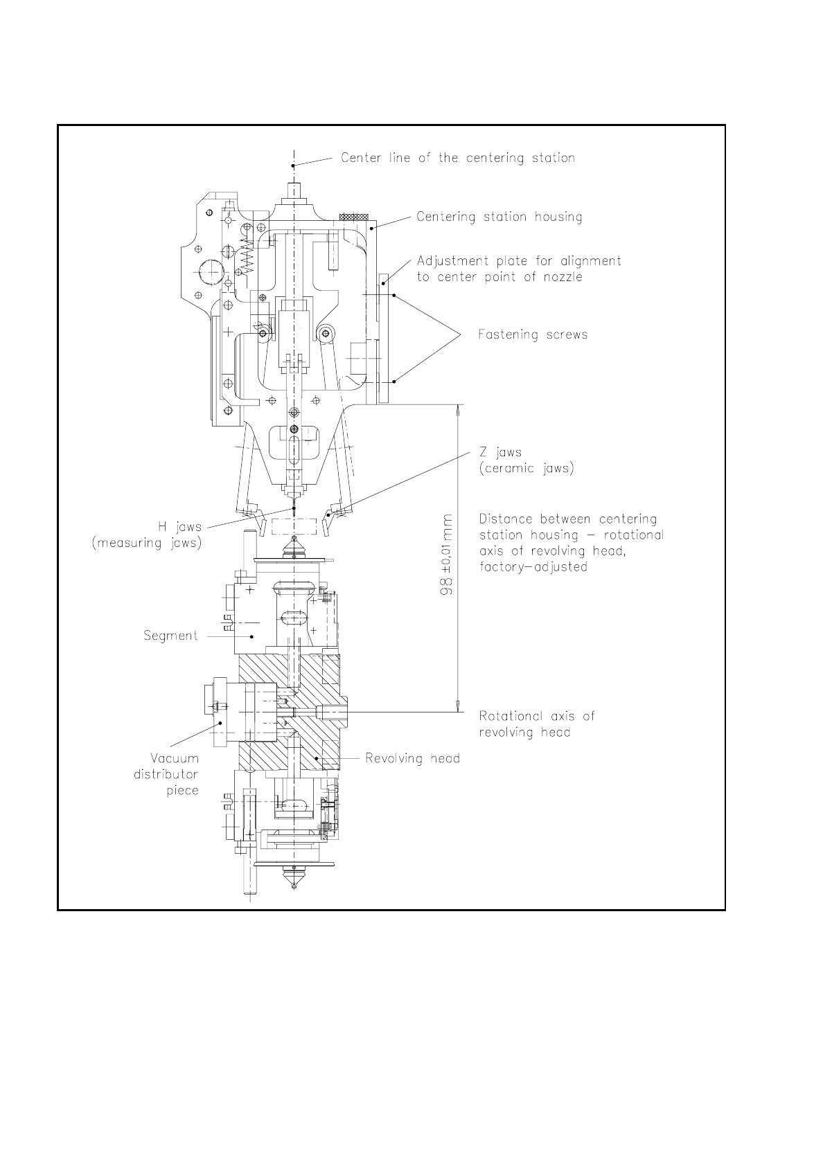
Fig. 9.7.3 Alignment of the mechanical centering station

SIPLACE 80S/F/G Service Manual 9 Revolver Head
Edition 04/97
9 - 73
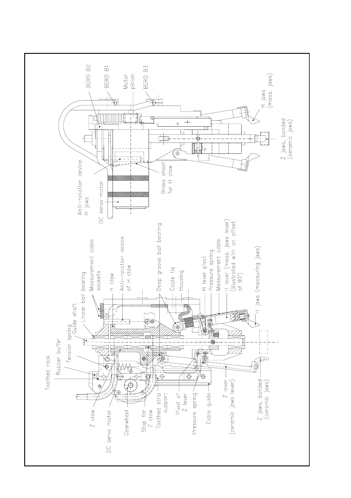
9.7.2 Structure of the Mechanical Centering Station
The mechanical centering station basically consists of the following components (see Fig. 9.7.4
and Fig. 9.7.5):
–
housing
–
direct current servo motor with pinion
–
toothed strip support
–
toothed rack with rubber buffer
–
ball guide for den toothed strip support
–
guide shaft and linear ball bearing for guiding the z and h claw
–
h claw with linear ball bearing, anti-rotation device and brake
–
z claw with linear ball bearing and anti-rotation device
–
1 tension spring to fetch the toothed rack back to the top end position (rest position of the centering station)
–
2 tension springs to move the claws to the lower end position - in other words, towards the segment
–
z lever pair (ceramic jaws lever pair) with deep-grooved ball bearings
–
h lever pair (measuring jaws lever pair) with deep-grooved ball bearings
–
3 beros:
B1: ceramic jaws bero
B2: end position bero
B3: measurement triggering bero
–
pressure springs for pressing the deep-grooved ball bearing of the jaws levers onto the running surface of
the h or z claws
–
z jaws pair (ceramic jaws pair)
–
h jaws pair (measuring jaws pair)
9 Revolver Head SIPLACE 80S/F/G Service Manual
Edition 04/97
9 - 74
Fig. 9.7.4 Structure of the mechanical centering station (sectional diagram)