80S-15贴片机.pdf - 第317页
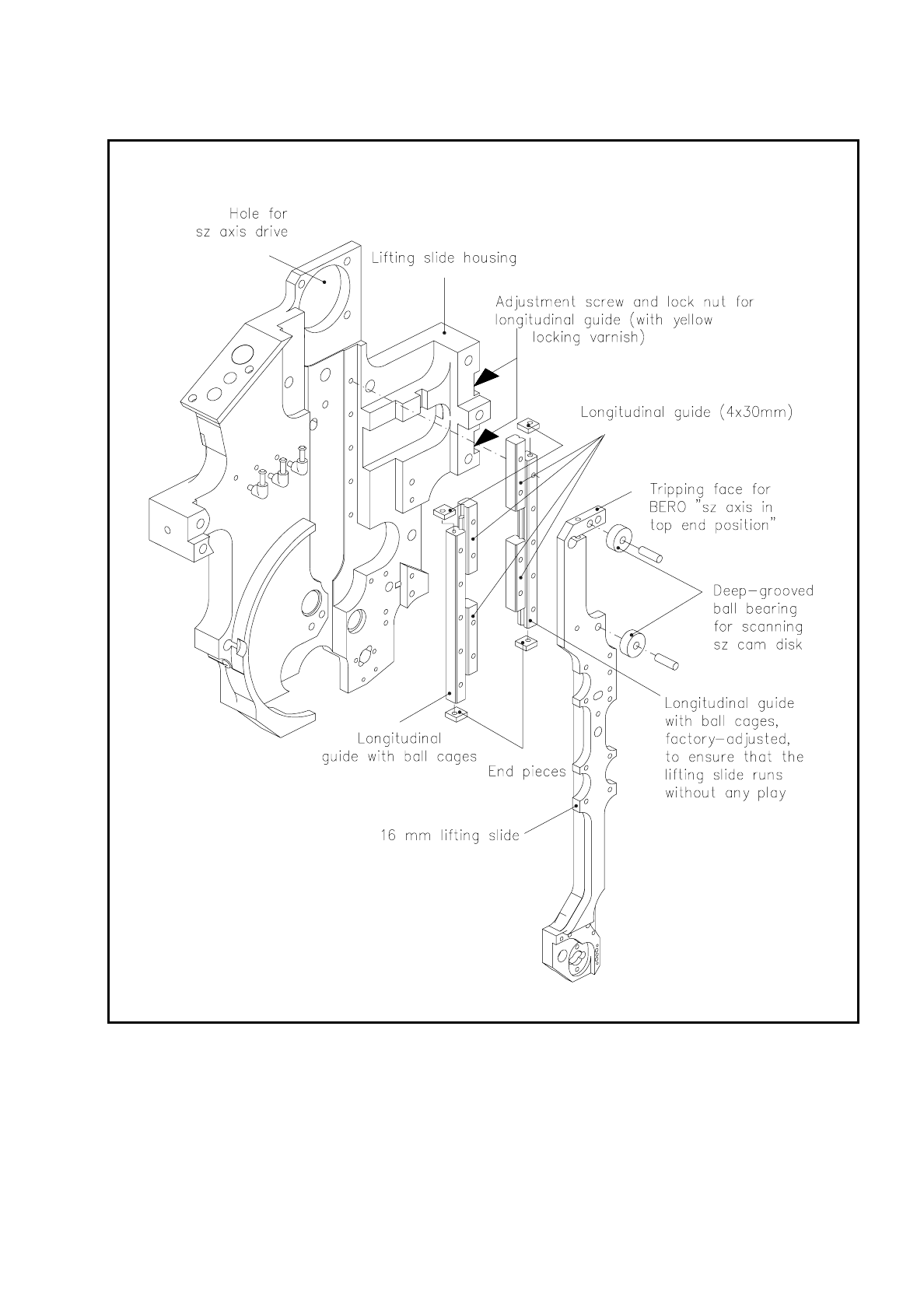
SIPLACE 80S/F/G Service Manual 9 Revolver Head Edition 04/97 9 - 33 Fig. 9. 5.7 16 mm lifting sl ide and longitudinal guide

9 Revolver Head SIPLACE 80S/F/G Service Manual
Edition 04/97
9 - 32
For the vacuum measurement which now follows the sealing piston is retracted - in other words, the segment
is open. If the measured vacuum value is better than the vacuum limit value for permissible contamination
with open segment specified in the MA data of the placement program (see Fig. 9.5.6), then the nozzle is
clogged. However a certain amount of contamination is permissible.
If the measured vacuum value exceeds the permissible limit value, the clogged nozzle will be segregated by
the program and the following error message displayed on the screen:
"The nozzle in the reject station for the gantry and segment is clogged."
Since the component can no longer be inserted, it will be added to the "Not done" list. If the nozzle is still
defective at the second check, the placement sequence will be aborted.
9.5.5 SZ axis
The following modules belong to the sz axis:
–
16 mm lifting slide (see Fig. 9.5.7)
–
bero: interrogation whether the sz axis has reached the top end position (see Fig. 9.5.1)
–
longitudinal guide of the lifting slide (see Fig. 9.5.7)
–
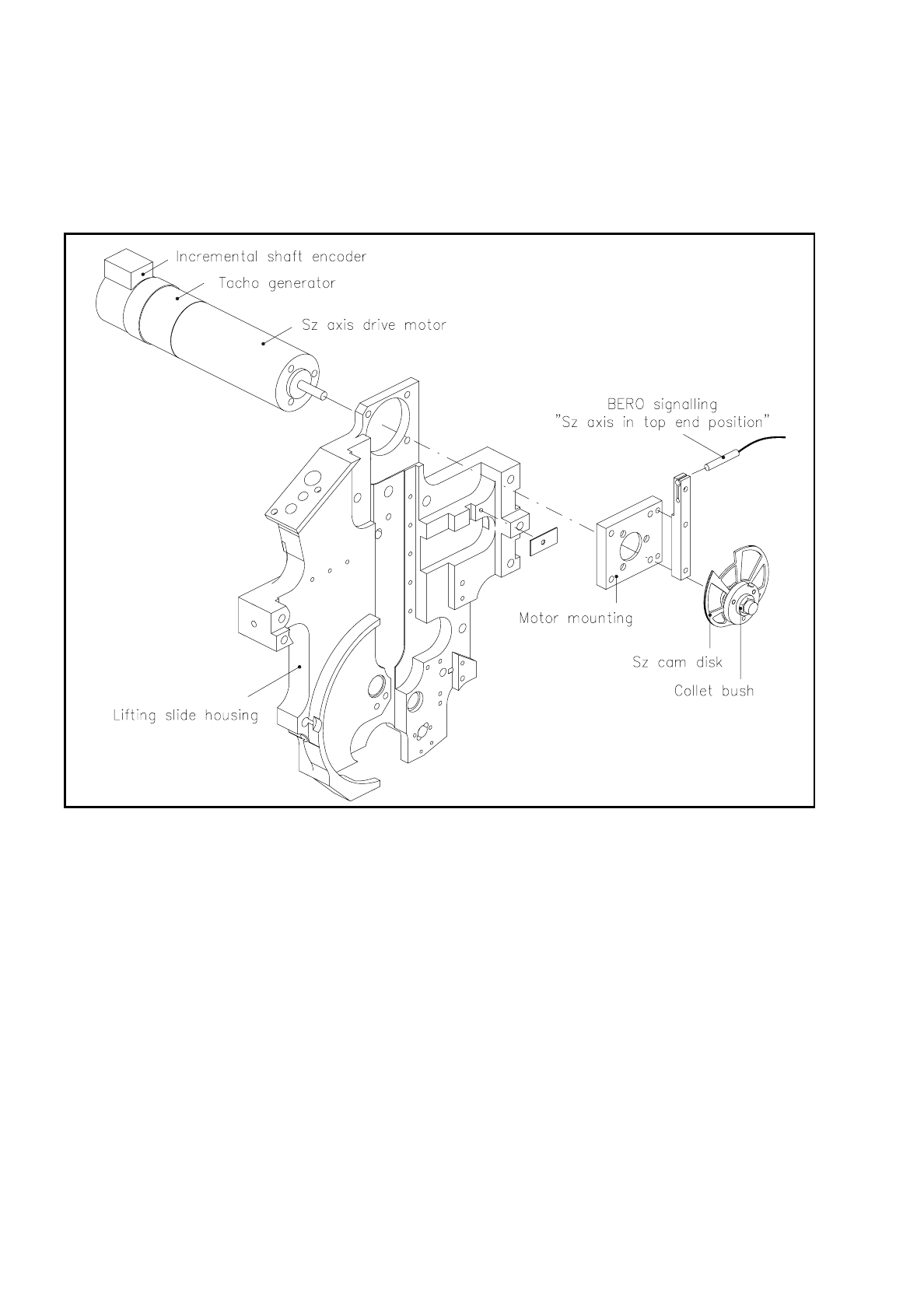
sz axis drive (see Fig. 9.5.8)
–
segment claw (see Fig. 9.5.9)
9.5.5.1 16 mm Lifting Slide
The 16 mm lifting slide slides in guide rails which are fastened to the lifting slide housing. Two deep-grooved
ball bearings roll on the sz-cam disk and thus convert the rotational movement of the sz-drive motor (see
Fig. 9.5.8) into a lifting movement of the lifting slide.
To pick up and insert components the lifting slide lowers the segment into revolver head station 1. To cycle
the revolver head on and thus to move the segments to the individual stations of the revolver head, the lifting
slide raises the segment up as far as the top end position. Once the sz axis reaches the top end position, the
tripping face (see Fig. 9.5.7) of the sz axis activates the bero "sz axis in top end position". The end
message generated by the bero signals that the revolver head can cycle on.
9.5.5.2 Longitudinal Guide of the Lifting Slide
Two rails which hold loose ball bearing cages at each end form the longitudinal guide of the lifting slide. The
rails are set in the factory to ensure the lifting slide runs without any play.
NOTE
Do not undo the yellow-painted locknuts and setting screws for the longitudinal guide of the lifting slide (see
Fig. 9.5.6), otherwise you will have to have the longitudinal guide reset in the factory.
SIPLACE 80S/F/G Service Manual 9 Revolver Head
Edition 04/97
9 - 33
Fig. 9.5.7 16 mm lifting slide and longitudinal guide
9 Revolver Head SIPLACE 80S/F/G Service Manual
Edition 04/97
9 - 34
9.5.5.3 SZ Axis Drive
Fig. 9.5.8 shows the drive for the sz axis, which powers the lifting movement of the lifting slide. The bero
signals when the lifting slide has reached the top end position.
Fig. 9.5.8 sz axis drive
The sz axis drive motor is a direct current servo motor with integrated tachometer generator and incremental
shaft encoder. The drive motor is fastened to the motor mounting with three M3 slotted screws, and this
mounting in its turn is screwed to the lifting slide housing with four M3 hexagon socket-head screws.
In addition, the holder for the bero which signals "sz axis in top end position" is fastened to the motor mount-
ing. A collet bush holds the sz cam disk on the drive shaft of the sz axis drive motor.
The travel of the sz axis for picking up and inserting a component is determined by the height of the compo-
nent. A continuous comparison of the actual and set heights of the component permits the travel speed of the
sz axis to be adapted to circumstances and the component is picked up from the conveyor with sensor stop
and mounted on the PCB.