80S-15贴片机.pdf - 第409页
SIPLACE 80S/F/G Service Manual 9 Revolver Head Edition 04/97 9 - 125 ● Mark th e connec ting wire s of the fe ed moto rs. ● Unsolder t he connec ting wires. ● Loosen t he two M 1.6 cou ntersun k head sc rews (se e item 1…
9 Revolver Head SIPLACE 80S/F/G Service Manual
Edition 04/97
9 - 124
●
Remove the retaining ring (see item 6 in Fig. 9.16.4) from the turning shaft of the toothed lever (see item 1
in Fig. 9.16.4).
●
Pull the turning axis of the toothed lever out of the hole and the ball bearings.
●
Insert the new toothed lever and secure it with the retaining ring.
●
Fit the new toothed wheel.
●
Lightly grease the teeth of the toothed levers with Unimoly GL82.
●
Ensure that the O-ring is grease-free and pull it on. Be careful not to stretch the O-ring when you pull it on.
●
After assembly, check the dynamic behavior and functioning of the turning station with reference to the
adjustment instructions and using the SITEST program.
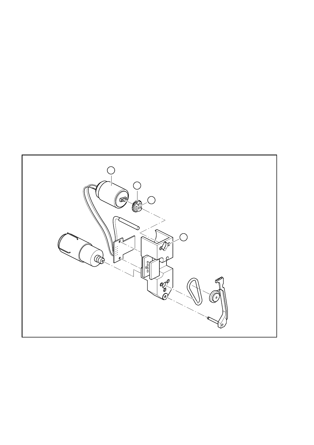
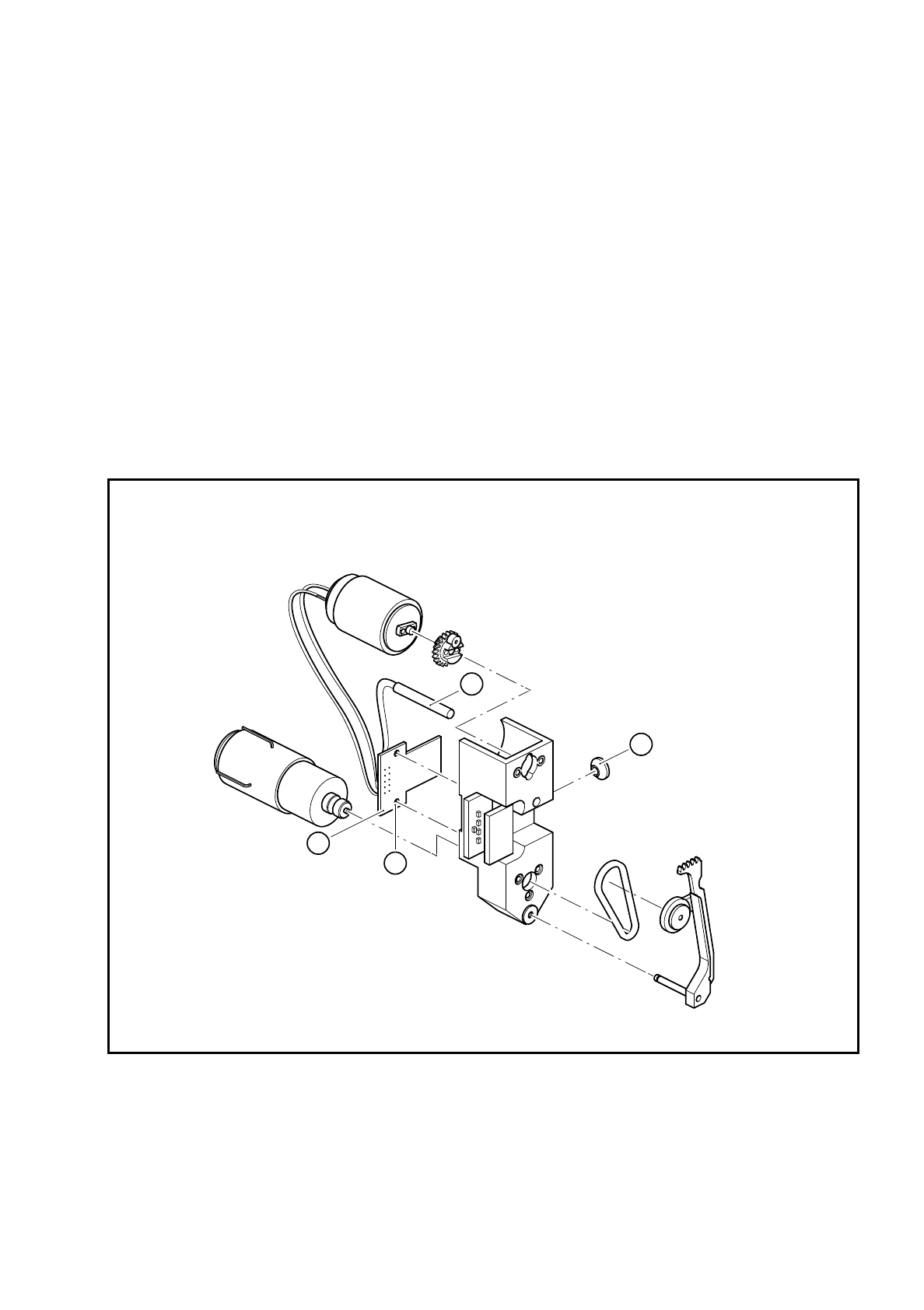
9.16.9 Replacing the complete DC motor (feed motor)
Fig. 9.16.5 Replacing the feed motor
Key to Fig. 9.16.5
●
Loosen the two M 1.4 fillister head screws (see item 2 in Fig. 9.16.5) for fixing the toothed wheel (see item
3 in Fig. 9.16.5).
●
Remove the toothed wheel.
1 2 M 1.6x3 countersunk head screws for fixing the
motor
3 Toothed wheel
2 2 M 1.4x4 fillister head screws for fixing the toothed
wheel
4 Feed motor
4
2
1
3
SIPLACE 80S/F/G Service Manual 9 Revolver Head
Edition 04/97
9 - 125
●
Mark the connecting wires of the feed motors.
●
Unsolder the connecting wires.
●
Loosen the two M 1.6 countersunk head screws (see item 1 in Fig. 9.16.5).
●
Replace the feed motor (see item 4 in Fig. 9.16.5).
●
Fix the motor and toothed wheel in place.
●
Pull heat-shrink sleeves over the connecting wires.
●
Solder the wires to the contact pins of the feed motors and carefully shrink on the heat-shrink sleeves.
●
Lightly grease the teeth of the toothed lever with Unimoly GL82.
●
After assembly, check the dynamic behavior and functioning of the turning station with reference to the
adjustment instructions and using the SITEST program.
9.16.10 Replacing the BERO
Fig. 9.16.6 Replacing the BERO
Key to Fig. 9.16.6
1 Proximity switch
2 ’Turn nozzle’ conversion board
3 Proximity switch clamp, M2x6 fillister head screws
4 2 M2x6 fillister head screws for fixing the ’Turn nozzle 1’ conversion board
1
4
2
3

9 Revolver Head SIPLACE 80S/F/G Service Manual
Edition 04/97
9 - 126
PLEASE NOTE:
It is not necessary to dismantle the turning station in order to carry out this work. The clamping screws can be
accessed from the front of the housing (see items 9 and 10 in Fig. 9.16.2 on page 9 - 120). On the other hand,
the clamping screw for the BERO on dp2 is covered by the amplifier board above it. For service purposes, first
remove the two M2 nuts and dismantle the amplifier board.
●
Loosen the clamping screw on the front of the housing.
●
Carefully remove the cable ties.
●
Loosen the two fillister head screws for fixing the ’Turn nozzle 1’ conversion board.
●
Unsolder the connecting wires of the BERO and pull them out of the hole.
●
Insert the new BERO and solder on the connecting wires.
●
Fix the conversion board in place.
●
Use the 0.15 mm feeler gauge to adjust the operating distance between the BERO and the toothed lever.
●
Clamp the BERO in this position.
●
After assembly, check the functioning of the BERO using the SITEST program.
9.16.11 Replacing the ’Turn nozzle’ conversion board
●
Loosen the two fixing screws (point 4 in Fig. 9.16.5 on page 9 - 124) for the ’Turn nozzle’ conversion board
Y0306.
●
Unsolder all the electrical connections on the feed motor, drive motor and BERO.
●
Solder all the connecting wires to the new board.
●
Check the terminal assignment with reference to drawing 1710491-Y3033-000-01-L-05-4 of the circuit dia-
grams.
●
After assembly, check the dynamic behavior and functioning of the turning station with reference to the
adjustment instructions and using the SITEST program.