80S-15贴片机.pdf - 第122页
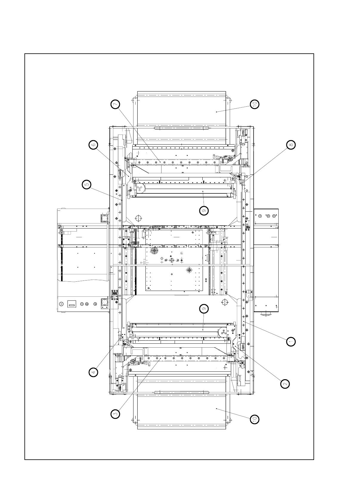
5 Gantries SIPLACE 80 S/F/G Service Manual Edition 04/97 5 - 4 Fig. 5.1.1 General view of gantries from above

SIPLACE 80 S/F/G Service Manual 5 Gantries
Edition 04/97
5 - 3
5.1 Introduction
5.1.1 Safety Instructions
This section provides a description of servicing work on the gantries of the SIPLACE 80S-20/F4.
The safety instructions to be found in Section 1 will also apply to all of the servicing work described in this sec-
tion.
5.1.2 Auxiliary Materials and Equipment
You will require the auxiliary materials and equipment listed in this section for all of the servicing work carried
out on the gantries. Additional materials or equipment are listed separately in the corresponding sections.
–
1 set of screwdrivers
–
1 set of hexagon socket spanners
–
1 set of socket spanners
–
1 pair of wire cutters, small
–
Screw locking varnish
–
1 digital voltmeter (class 1.5)
–
Spare parts catalog SIPLACE 80S/80F/G
–
Instruction Manual ’Measuring Belt Tension’
5.1.3 General Comments
The SIPLACE 80S placement machine is equipped with a pair of x-gantry and y-gantry axes which are
mechanically independent of each other. The SIPLACE 80F placement machine as well as the adhesive
application machine possess one x- and one y-gantry axis.
The SIPLACE 80F/G gantries are of identical design. For this reason all of the servicing work which is
described in the following section will be presented on the basis of just one gantry.
The x and y axes are powered by direct current servo motors.
The position measurement system uses linear scales. For the x and y directions these are fixed directly to the
gantry axes. A read head scans the linear scales and in this way determines the position of the axis. This pro-
cedure is referred to as direct position measurement.
Power is transmitted from the direct current motors to the gantries via toothed belts and deflection.
5 Gantries SIPLACE 80 S/F/G Service Manual
Edition 04/97
5 - 4
Fig. 5.1.1 General view of gantries from above

SIPLACE 80 S/F/G Service Manual 5 Gantries
Edition 04/97
5 - 5
5.1.4 Preparatory Work
We recommend that you always remove the components table before working on the gantry (see Section
12.1 “Removing and Installing the Component Change-over Table“). This will make your servicing work much
easier to perform.
5.1.4.1 Removing and Installing the Changeover Table
●
Disconnect the changeover table’s electrical and pneumatic connections.
●
Open the locking lever.
●
With a lift truck lift the components table over the taper pins and move the changeover table out of the
machine.
●
To re-install the changeover table proceed in the reverse sequence of operations.
Key to Fig. 5.1.1.
1 Y axis, gantry 2 2 Y-axis drive motor, gantry 2
3 X axis, gantry 1 4 X-axis drive motor, gantry 1
5 Y axis, gantry 1 6 Y-axis drive motor, gantry 1
7 X axis, gantry 2 8 X-axis drive motor, gantry 2
9 Used tape cutters 10 Components tables