80S-15贴片机.pdf - 第418页
9 Revolver Head SIPLACE 80S/F/G Service Manual Edition 04/97 9 - 134 Fig. 9.18.1 Screwdriver 1 Key to Fig . 9.18.1 1 D C motor, comp lete 5 S egment cl aw / 5a Screwdrive r blade 2 S top / 2 a Cove r plate 6 BER O 3RG460…

SIPLACE 80S/F/G Service Manual 9 Revolver Head
Edition 04/97
9 - 133
9.18 Service work on screwdriver 1
9.18.1 Tools, equipment and consumables
9.18.2 Spare parts
9.18.3 Screwdriver 1 - replacing the motor
●
Dismantle the encoder housing as described in Section 9.13 on page 9 - 103.
●
Loosen the two M2.5 x 5 countersunk screws for fixing the link (see item 7 in Fig. 9.18.1)
●
Carefully remove the link from the parallel pins on the lifting carriage housing (see item 8 in Fig. 9.18.1).
●
Loosen the two M 1.6 x 8 countersunk screws for fixing the cover plate (see item 2a in Fig. 9.18.1) and the
stop (see item 2 in Fig. 9.18.1).
●
Carefully remove the stop from the two parallel pins.
●
Loosen the two M 1.4 x 5 fillister head screws on toothed wheel 1 (see item 3 in Fig. 9.18.1).
●
Pull the toothed wheel from the motor shaft.
●
Strip the heat-shrink sleeves from the electrical connections of the DC motor (see item 1 in Fig. 9.18.1)
and unsolder the cable.
●
Loosen the two M 1.6 x 3 fillister head screws for fixing the DC motor (see item 1 in Fig. 9.18.1).
●
Pull the DC motor out from the back.
From item number
Set of screwdrivers
Set of hexagon socket-head screwdrivers
Soldering iron
Hot air gun
Scribing iron
0.2 mm feeler gauge
Unimoly GL82 lubricating grease, 25 g
00313490-01
Ethyl alcohol
Number in
Fig. 9.18.1.
From item number
DC motor, complete
1 00323190S01
Stop
2 00201237-05
Toothed wheel 1 - placement
3 00318185-01
Cable bracket
4 00201234-01
Segment claw
5 00201244-04
BERO 3RG4603-2AB03 (without sheath)
6 00313517-01
9 Revolver Head SIPLACE 80S/F/G Service Manual
Edition 04/97
9 - 134
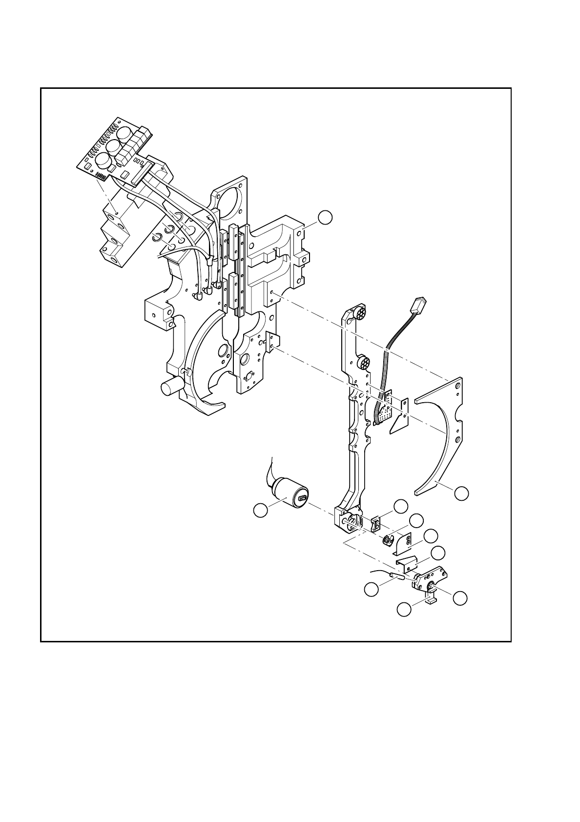
Fig. 9.18.1 Screwdriver 1
Key to Fig. 9.18.1
1 DC motor, complete 5 Segment claw / 5a Screwdriver blade
2 Stop / 2a Cover plate 6 BERO 3RG4603-2AB03
3 Toothed wheel 1 7 Link
4 Cable bracket 8 Lifting carriage housing
1
2
3
2a
4
5a
7
5
6
8
SIPLACE 80S/F/G Service Manual 9 Revolver Head
Edition 04/97
9 - 135
●
Insert the new DC motor and fix in place.
●
Push new heat-shrink sleeves over the motor cable.
●
Solder the cable to the DC motor. Check that the polarity of the terminals is correct:
Cable colors: red = +, black =
−
●
Carefully shrink on the heat-shrink sleeves using the hot air gun.
●
Lightly grease the teeth of toothed wheel 1 with Unimoly GL82.
●
Fix toothed wheel 1 in place.
Check the position of the screwdriver blade with respect to toothed wheel 1 against the following diagram:
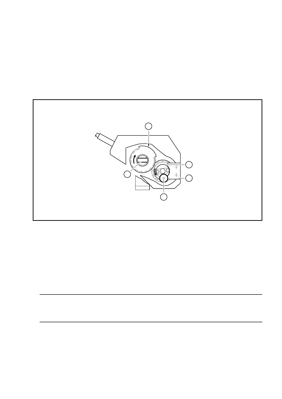
Fig. 9.18.2 Position of toothed wheel 1 and the screwdriver blade during reassembly
Key to Fig. 9.18.2
●
Fix the stop with the cover plate
PLEASE NOTE:
After assembly, the star can only turn the segments if the head was assembled while the screwdriver
blade was in the horizontal position (see item 2 in Fig. 9.18.2).
●
Check the functioning of screwdriver 1 with reference to the adjustment instructions and using the SITEST
program.
1Stop
2 Toothed wheel 1
3 The BERO trigger surface is in the top position
4 The screwdriver blade is horizontal
5 The small stop wheel of toothed wheel 1 is against the stop
3
2
1
5
4