80S-15贴片机.pdf - 第211页
SIPLACE 80 S/ F/G Service M anual 7 Components Table Edition 04/97 7 - 29 7.5. 2.5 Testing the Connection Sock ets wit h the Feed er Position Te ster In the cas e of e rror mes sage No. 43 you can carry ou t the fol lowi…

7 Components Table SIPLACE 80 S/F/G Service Manual
Edition 04/97
7 - 28
●
Make sure that the components changeover table functions correctly with the new communications unit.
Please note the following note.
NOTE:
The error message "Communication with table interrupted" can occur both at starting and also during the
placement sequence at component pick-up from this table. For this reason, to check this start a (self-writ-
ten) placement program with components being picked up from the location which is to be tested.
If the SITEST program is used for testing, no corresponding error message will be issued.
–
No error message after replacement of the components changeover tables: start the placement
sequence.
7.5.2.4 Replacing Cable Y559-W1
●
Open the protective cover, pull the protective cover at the components loading point upwards and away.
Now move the placement head by hand until it is within the PCB transportation area:
Please note at this time the CAUTION note in section 7.2 "Fault Characteristics"!
●
Cut off the empty tapes - if this has not already been done- at the front end of the module. All modules and
the tape reels will remain where they are in order that their allocations do not get changed.
NOTE:
If you have already unintentionally removed the tape reels, to restore their previous allocations proceed as
described in the User’s Manual, Section 9, under "Components tables".
●
Open the clamping lever, undo the plug connections (X37, mains plug and, if applicable, the pneumatics
connection) at the machine base and with a lift truck carefully remove the components changeover table
as described in the User’s Manual, Section 8.
●
The front panel of the communications unit has already been removed in the course of fault location (see
above) and the plug connection of the cable Y559 -W1 in the communications unit undone.
●
Remove the defective cable, install the new cable Y559-W1, reconnect the plug connection in the commu-
nications unit, making sure that it is firmly seated.
●
Refit the components changeover table, close the clamping elements, reconnect the plug connections
(X37, mains plug and, if applicable, the pneumatics connection) at the machine base.
●
Switch on the machine and start the placement sequence.

SIPLACE 80 S/F/G Service Manual 7 Components Table
Edition 04/97
7 - 29
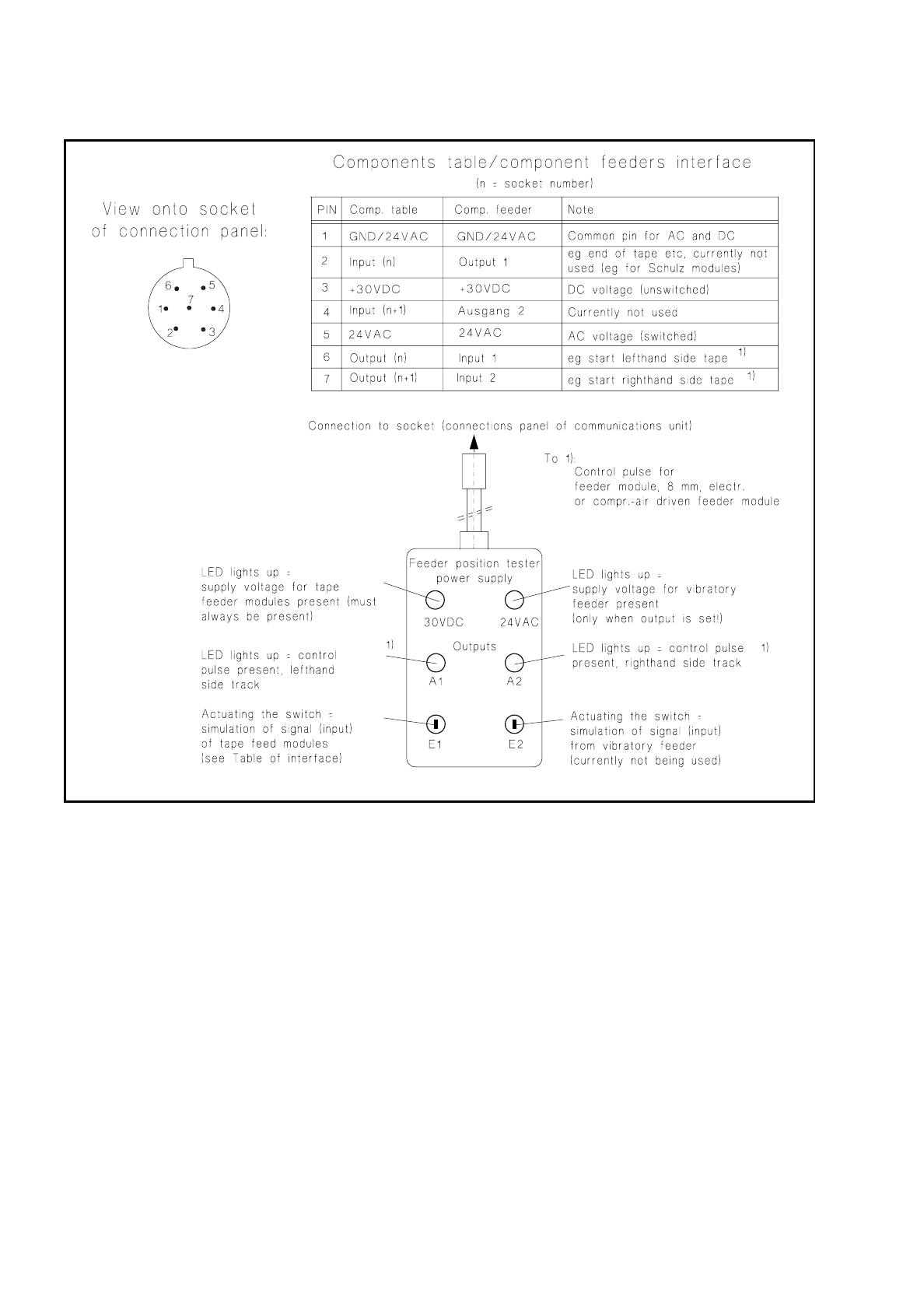
7.5.2.5 Testing the Connection Sockets with the Feeder Position Tester
In the case of error message No. 43 you can carry out the following tests on the individual connection sockets
of the communications unit with the aid of the feeder position tester:
–
30 VDC voltage (always present at the socket),
–
a.c. voltage for the vibratory feeders (present only when the feeder is being operated),
–
control pulse (output signal) for tape cycle with tape feeder module 8 mm electrical, V2 (new version),
–
control pulse (output signal) for solenoid valve in the compressed air feeder module.
NOTE:
For the purposes of fault location the vibratory feeders can also be activated via the station software:
proceed as follows: pull out the plug of the vibratory feeder
→
connect up the feeder position tester
→
menu
"Component feeding"
→
"Location"
→
"Vibrate linear feeder"
→
Return. The output for the vibratory feeders
will remain set until you cancel the function "Vibrate linear feeder" (toggle function).
For further fault location, use the SITEST program. In this case use the feeder position tester as follows:
●
Select "Abort placement", quit the placement program and load the SITEST program.
●
Testing the +30 VDC voltage for the tape feeder modules:
●
Pull out the plugs of the tape feeder modules one after the other from the connections panel, each
time plugging in the feeder position tester (see Fig. 7.5.2):
●
The +30 VDC supply voltage must always be present at the socket, and therefore the feeder position
tester LED (see Fig. 7.5.2) must light up each time.
●
Testing the a.c. voltage for the vibratory feeders:
●
Pull out the plug of one vibratory feeder, connect the feeder position tester to the socket thus freed.
●
Set the output for this track by means of the SITEST program by making the following selection:
"Functions"
→
"BE table"
→
"Single function"
→
"Adr. or track"
→
"Lin. feeder".
The voltage is applied for approx. 200 ms. The corresponding LED on the feeder position tester must
light up briefly (see Fig. 7.5.2), provided the potentiometer under the socket has not been set to "0"
→
setting the potentiometer: see the section below.
NOTE:
From SITEST program version 1.64 onwards the duration of vibration is configurable.
●
Check all sockets of the connections panel in this way.
●
Testing the output (= control pulse) for the module 8 mm electr. and the compressed air feeder
module:
●
Connect the feeder position tester to the corresponding socket and set the output: "Functions"
→
"BE
table"
→
"Single function"
→
"Adr. or track"
→
"Output".
Check the activation of the LED on the feeder position tester for the lefthand and righthand tracks
(Fig. 7.5.2).
7 Components Table SIPLACE 80 S/F/G Service Manual
Edition 04/97
7 - 30
Fig. 7.5.2 Feeder position tester and assignments of the sockets on the connections panel
●
If no voltage or output is detected during this testing at any one socket or at all of them, replace the com-
munications unit as described in the corresponding section below.
●
If voltage and / or the signal are present at the socket, this indicates a fault within the feeder module or in
the connecting cable of the module.
●
With vibratory feeders, before making any fault correction in the module check first the setting of the poten-
tiometer on the connections panel (see section 7.5.2.6 on page 7 - 31).