80S-15贴片机.pdf - 第162页
6 PCB Han dling SIPLACE 80 S/F/G Servic e Manual Edition 01/96 6 - 26 Fig. 6.5.1 Removing the retainers and compression spr ings Key to Fig . 6.5.1 1 S ide panel , fixed s ide 2 R etainer 3 C omb gui de 4 DU str ip s 5 G…

SIPLACE 80 S/F/G Service Manual 6 PCB Handling
Edition 01/96
6 - 25
6.5 Retainers and Compression Springs
Spare parts, auxiliary materials and equipment
Retainer, righthand, Item No. 00317678-02
Retainer, lefthand, Item No. 00317679-02
Compression spring 0.8 * 8.8 * 32 V2A, Item No. 00200342-01 (order 2 for each conveyor side)
6.5.1 Removing retainers and compression springs
NOTE
OOO
You should also comply with the safety instructions in Chapter 1.
●
Adjust the board conveyor to the maximum width setting when you change the retainer on the fixed side of
the conveyor.
●
For board transport, select ’Half board conveyor width’ when you change the retainer on the movable side
of the conveyor.
●
Move the gantry or gantries to outside the board transportation area.
●
Lower the lifting table.
●
Switch off the machine at the main switch and disconnect it from the main power supply.
●
Make sure that the machine cannot be switched on while you are carrying out servicing work.
●
Remove the rocking lever (A).
●
Remove the three DU strips (B) and the two comb guides on the outside. To do so remove the M3
recessed-head screws and hexagon socket screws.
●
Undo and remove the M3 recessed-head screws which fasten the blocks (D) and remove the two com-
pression springs.
●
Remove the guide strip (E).
●
Swing the retainer outwards (F) and remove it.
6 PCB Handling SIPLACE 80 S/F/G Service Manual
Edition 01/96
6 - 26
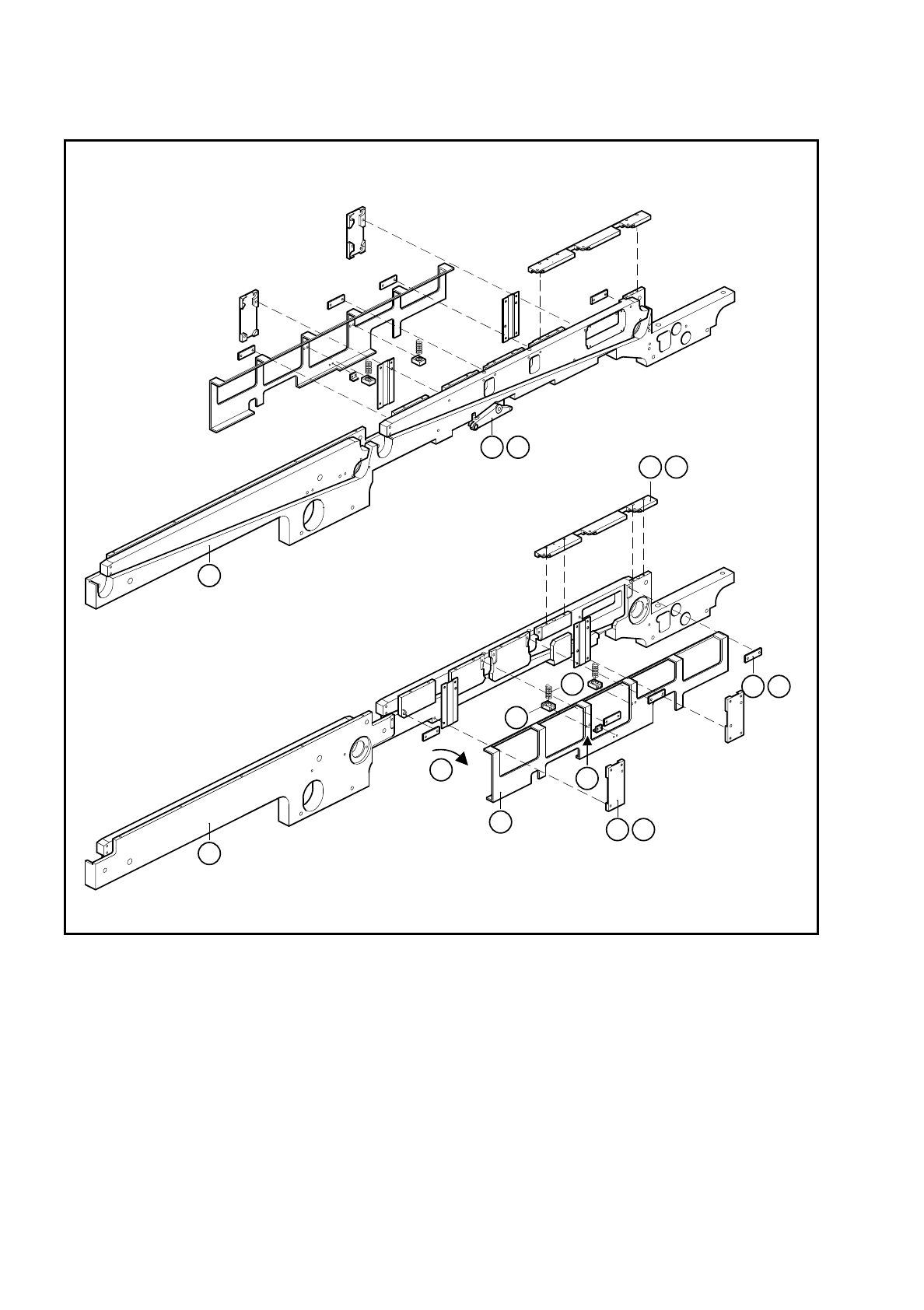
Fig. 6.5.1 Removing the retainers and compression springs
Key to Fig. 6.5.1
1 Side panel, fixed side 2 Retainer
3 Comb guide 4 DU strips
5 Guide rail 6 Compression spring
7 Block 8 Rocking lever
9 Side panel, movable side
1
9
2
4 B
5 E
7
6
F
8 A
3 C
D

SIPLACE 80 S/F/G Service Manual 6 PCB Handling
Edition 01/96
6 - 27
6.5.2 Fitting the retainers and compression springs
The retainers and compression springs should be fitted back in the reverse sequence of operations.
NOTE
Before fitting the compression springs check their length. When unloaded they should be 32 mm. If this is not
the case change the springs, always doing so in pairs for each side of the conveyor.
●
Align the guide rails as described in Section 6.6, Page 6 - 29.
6.5.3 Function test
Under the
Conveyor functions
menu carry out a function test with the boards.