80S-15贴片机.pdf - 第339页
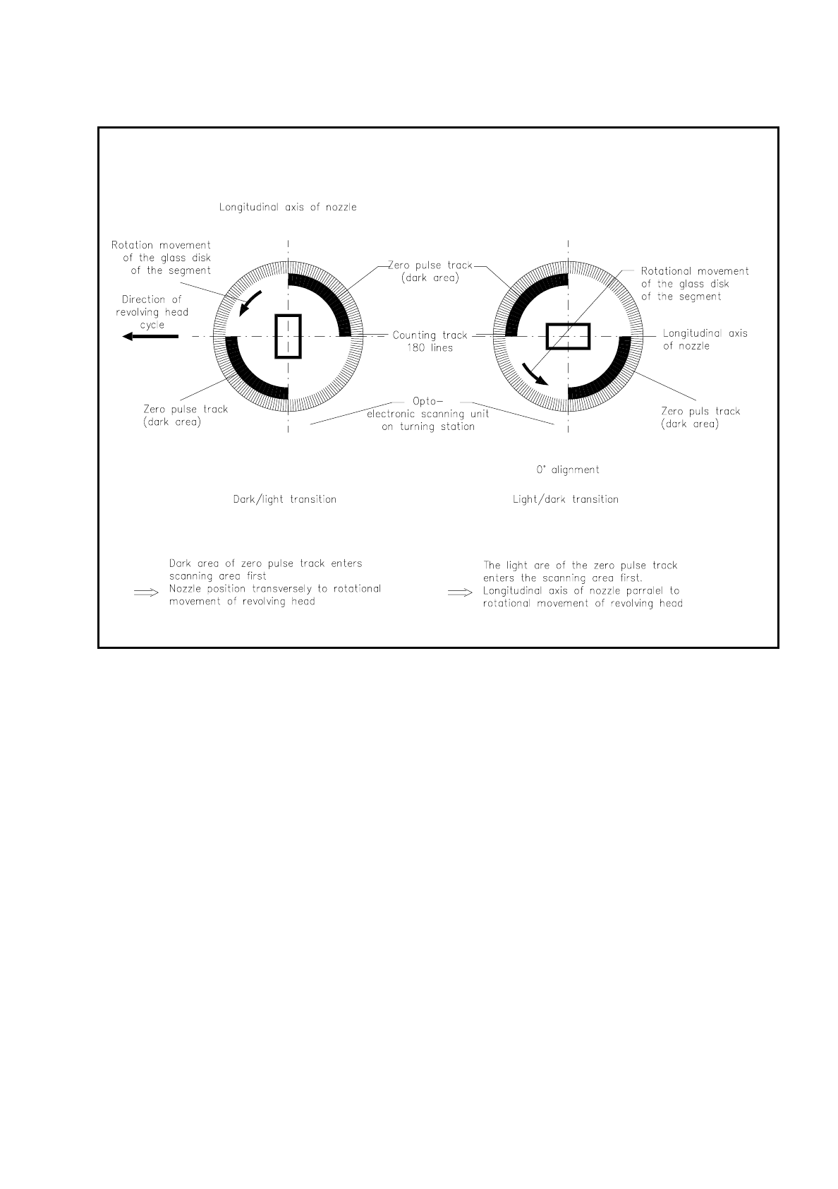
SIPLACE 80S/F/G Service Manual 9 Revolver Head Edition 04/97 9 - 55 Fig. 9.6.9 P osition of t he nozzle longitudinal axis with respect t o the direction of revolver head movement These an alog signals are ampli fied with…
9 Revolver Head SIPLACE 80S/F/G Service Manual
Edition 04/97
9 - 54
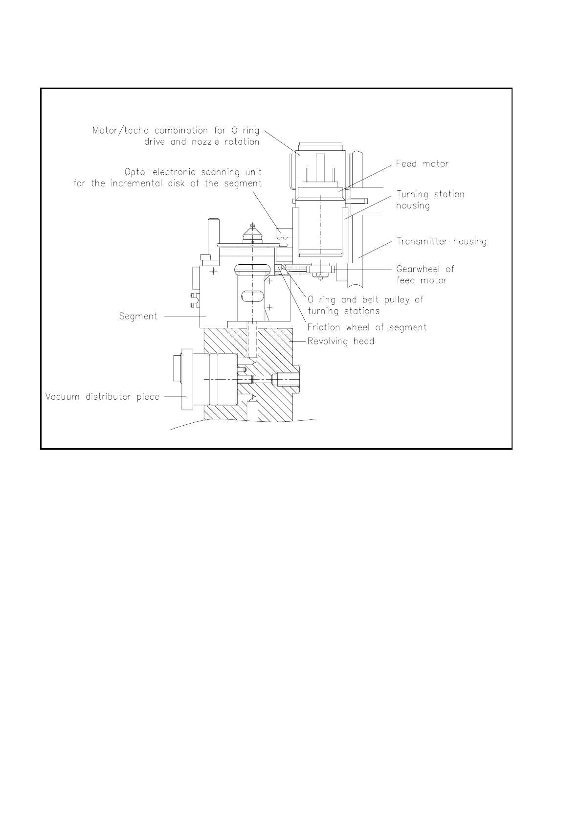
Fig. 9.6.8 Docking the turning station at the segment friction wheel
9.6.3.2 Opto-Electronic Scanner Unit of dp1 and dp2
The position of the nozzle is determined by opto-electronic scanning at each turning station. It consists of 5
photo diodes at the transmitting end and 5 photo transistors at the receiving end. The glass disk of the seg-
ment rotates with its zero pulse track between them in order to determine the position of the nozzle and also
with a 180-line counter track at the edge of the glass disk in order to turn the component precisely into the
required position. The signals from the photo transistors supply in each case two track signals for tracks A and
B and one signal for the zero pulse.
SIPLACE 80S/F/G Service Manual 9 Revolver Head
Edition 04/97
9 - 55
Fig. 9.6.9 Position of the nozzle longitudinal axis with respect to the direction of revolver head movement
These analog signals are amplified with the amplifier board on the encoder housing front (see Fig. 9.6.4) and
multiplied on the quintuple board and converted into square-wave signals for the purposes of evaluation in the
axis controllers. The track signals are illustrated in Fig. 9.6.15.
Fig. 9.6.10 shows the position of the longitudinal axis of the nozzle with respect to the zero pulse track.
Depending on whether the opto-electronics registers a light-dark or dark-light transition of the zero pulse
track, the current nozzle position is detected and then the nozzle turned into the required position.
The resolution of the electronic positioning system is 10 digits per degree.
9 Revolver Head SIPLACE 80S/F/G Service Manual
Edition 04/97
9 - 56
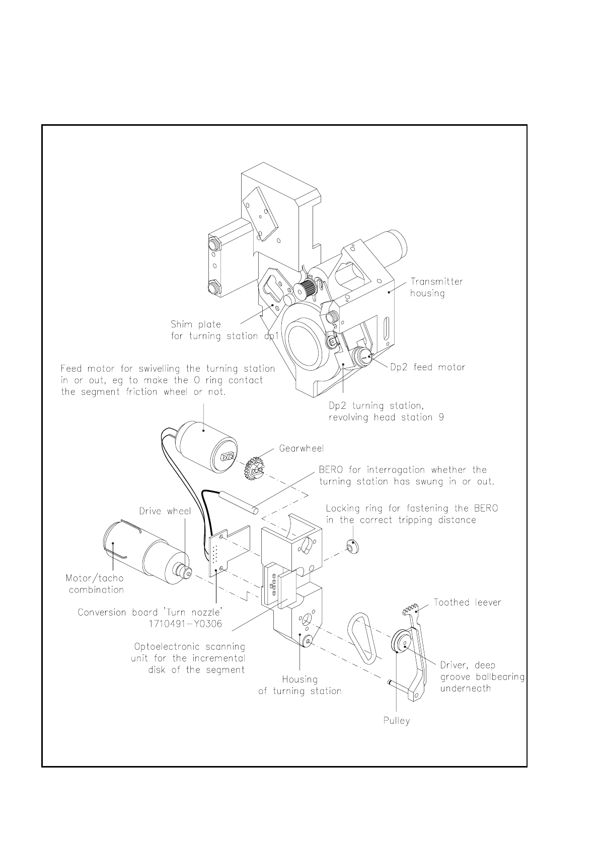
9.6.4 Turning Station dp2
Fig. 9.6.10 Position and structure of turning station dp2