80S-15贴片机.pdf - 第128页
5 Gantries SIPLACE 80 S/F/G Service M anual Edition 04/97 5 - 10 ● Fit the ri bbon cabl e hold er and pl ug the t wo ribbon cables into the c onvers ion boar d. ● Now carry out a c omplete a djustm ent of t he x axi s (s…
SIPLACE 80 S/F/G Service Manual 5 Gantries
Edition 04/97
5 - 9
5.2.3 Installation
●
Insert the new motor through the flange and pull the toothed belt carefully over the motor pinion.
●
Mount the motor using the four hexagon socket screws and pretension the toothed belt.
NOTE
Make sure that the connection cable will not be subjected to rubbing over the entire travel range of the gantry.
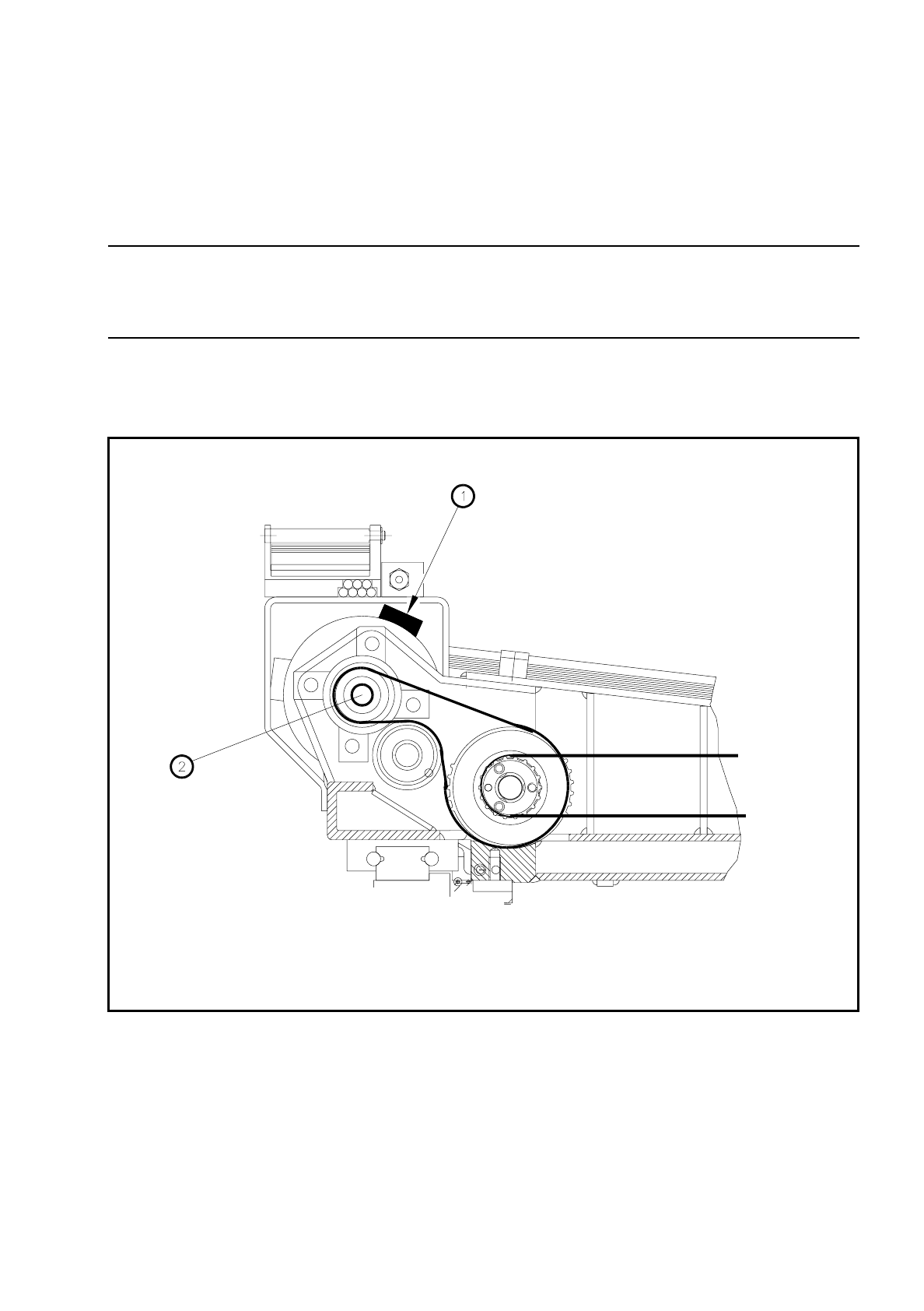
The motor connection cable must be in the 2 o’clock position as seen from the motor shaft (see Fig. 5.2.2).
●
Now adjust the tension of the toothed belt using Table 5.2 - 1 and tighten up the screws.
●
Plug the motor connection plug into the conversion board.
●
Attach the connection cable to the motor using the cable ties.
Fig. 5.2.2 Position of the x-motor connection cable
Key to Fig. 5.2.2.
1 2 o’clock position of the connection cable 2 Motor shaft

5 Gantries SIPLACE 80 S/F/G Service Manual
Edition 04/97
5 - 10
●
Fit the ribbon cable holder and plug the two ribbon cables into the conversion board.
●
Now carry out a complete adjustment of the x axis (see adjustment instructions).
Toothed belt Endless toothed belt 12ATS5/280-E6/8
Adjustment with belt tension meas. device
Frequency prior to cont. operation:
460 Hz ± 1 Hz
Frequency after cont. operation:
440 Hz ± 1 Hz
Table 5.2 - 1 Required setting for the x-axis endless toothed belt

SIPLACE 80 S/F/G Service Manual 5 Gantries
Edition 04/97
5 - 11
5.3 Replacing the Endless and Cut Toothed Belt of the
X-Axis
5.3.1 Spare Parts, Auxiliary Materials and Equipment
–
1 Brecoflex toothed belt, from item no. 00302872-02 (cut toothed belt)
–
1 Synchroflex toothed belt 10T5/295, from item no. 00304890-0118549-01 (endless toothed belt)
–
1 Belt tensioning key for SIPLACE 80, from item no. 02108015-01
–
Belt tension measuring device, from item no. 00326015-01
5.3.2 Removal
NOTE
OOO
You should comply with the safety instructions given in Section 1.
●
Undo the four hexagon socket screws of the drive motor and remove the entire X-drive motor. (See Sec-
tion 5.2).
●
Remove the placement head (see Section 9).
●
Loosen the endless toothed belt of the X axis (see Section 5.3.1).
●
Undo the fastening screw (hexagon socket screw) of the belt wheel by gripping the opposite end with a
standard screw driver (see Fig. 5.3.1).
●
Remove the belt wheel together with the shaft by carefully pressing the shaft out from behind and lifting the
belt wheel up and away.
●
Watch out for the belt wheel shim washer.
NOTE
O
Each belt wheel is adjusted separately with its own shim washer. This shim washer must be reused with its
own belt wheel if the belt is to run precisely.
●
Now remove the defective endless toothed belt.