80S-15贴片机.pdf - 第193页
SIPLACE 80 S/ F/G Service M anual 7 Components Table Edition 04/97 7 - 11 7.2 Fault Ch aracterist ics Carry out prelimi nary fau lt location with the aid of fault cha racteristic s liste d belo w and th eir poss ible c a…
7 Components Table SIPLACE 80 S/F/G Service Manual
Edition 04/97
7 - 10
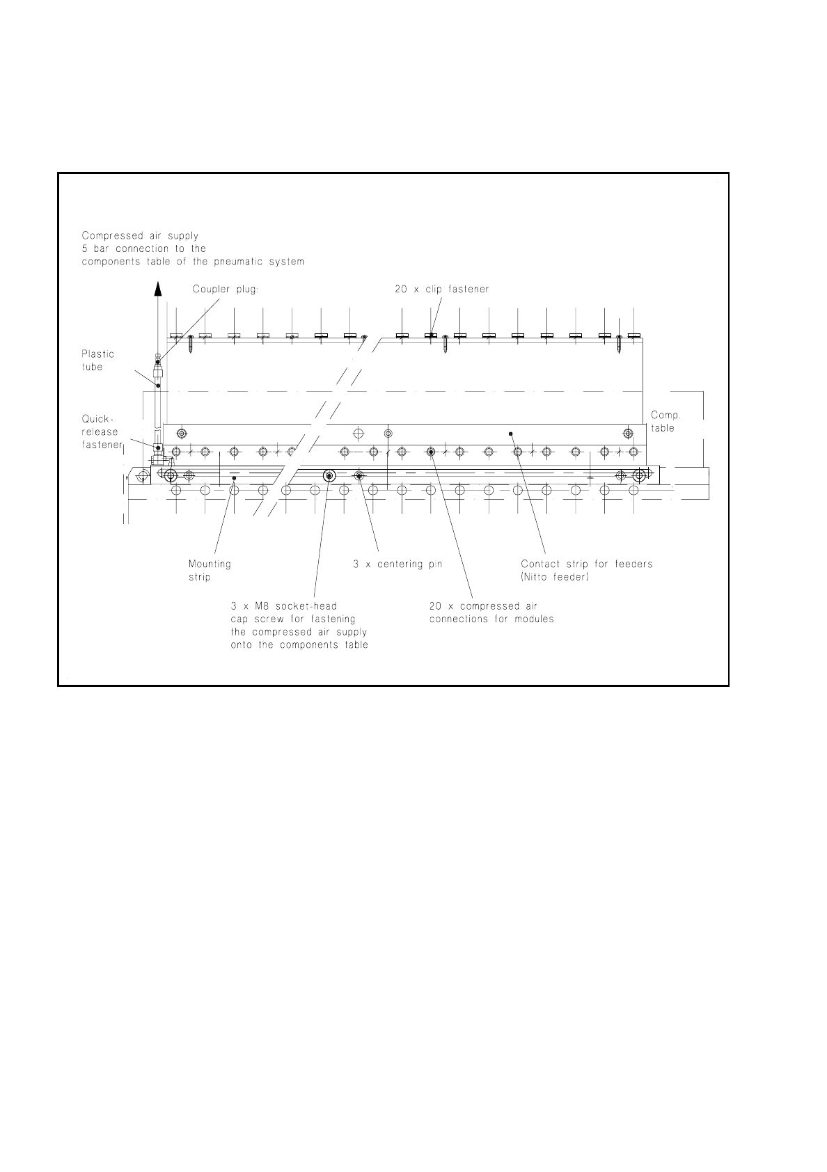
7.1.5 Components Table Compressed Air Supply Unit (Option)
Fig. 7.1.5 Components table compressed air supply, top view
When compressed air feeder modules (= feeder modules which operate using compressed air) are to be used
the optional "components table compressed air supply unit" (see diagram above) together with the "compo-
nents table pneumatic system" (see Fig. 7.7.1) is installed in the SIPLACE 80 S machine.
●
This "components table compressed air supply unit" (= compressed air distributor strip) is fitted in a
defined position on the longer side of the changeover components table (see Fig. 7.1.2) by means of 3
centering pins and fastened down to the components table with 3 hexagon socket-head cap screws M8.
●
Each compressed air feeder module after installation at the components table is attached to the com-
pressed air distributor strip by means of a clip fastener. When the module is used the corresponding
plunger is pressed downwards into the compressed air distributor strip which assures continuous availabil-
ity of compressed air at the module.
●
Connection to the power supply is at the corresponding socket on the connections panel (communications
unit).
●
Actuation of the solenoid valves in the feeder module operates the compressed air branch in the module
and the components are conveyed onwards, separated into singles and brought into the pick-up position.

SIPLACE 80 S/F/G Service Manual 7 Components Table
Edition 04/97
7 - 11
7.2 Fault Characteristics
Carry out preliminary fault location with the aid of fault characteristics listed below and their possible causes.
The order in which the possible causes are given here represents the best way of proceeding as far as the
amount of work and the probability of the fault are concerned.
For detailed information on further location and correction of the fault please refer to the corresponding sec-
tion of this Service Manual.
DANGER
QQQ
Please note with all fault correction work the safety instructions in the User’s Manual.
Please note in addition:
In the machine base interior the 400 VAC operating voltage is still present in certain modules even when
the main switch is switched off.
All work in the machine base interior must therefore only be carried out by authorized persons who have had
the appropriate training.
During all work in the machine base interior you must comply with the special VDE 0113 electrical safety
regulations and disconnect the machine as soon as possible from the mains supply.
This also applies to all work on the power supply unit of the components changeover table (transformer T1
below the components table).
7.2.1 Faults with Error Message
–
With "Track error" the corresponding placement head moves over the board conveyor so that the feeder
modules can be topped up.
–
In the menu "Components feed" after you select the function "Display track errors" you will be provided
with a complete overview of all errors which have occurred. These errors will be accumulated if they are
not deleted after correction (setter function "Set all full").
–
The current error is displayed on the top line.
–
More detailed information on track error menus 1 and 2 will be found in the User’s Manual.

7 Components Table SIPLACE 80 S/F/G Service Manual
Edition 04/97
7 - 12
NOTE
Please note the following, before you switch the machine off in the course of fault location and correction
work, or make a change in the compressed air circuit:
First quit the track error menu with "Abort placement" so that all components picked up at the revolving head
in the course of the reference run can be dropped into the rejects container.
After this switch off the machine at the main switch, or subsequently modify the compressed air circuit or the
compressed air unit (for example, in connection with the "components table pneumatic system"). Otherwise
the components will drop uncontrolledly into the machine and will there be the cause of further faults!
If you are however able to correct the fault without taking the steps just mentioned - for example, by correcting
a feeder module fault - then the components will remain picked up. Once you have corrected the fault, select
from within the "Track errors 1/2" menu the function "Continue placement".
CAUTION
OO
After "Abort placement" the placement head will be in the stand-by position above the corresponding compo-
nents supply unit!
Before removing the feeder modules or moving out the components changeover table you must therefore
always first move the placement head by hand to a position within the PCB conveyor.
To do so without damaging anything, hold the placement head (when the machine is switched off) only by the
handle or press against a suitable part of the gantry carriage.
Please note: A minimum separation of the axes must be complied with (crash switch!) or restored before the
machine is switched back on! For this reason when the conveyor width is narrow always position only one
axis by hand above the board conveyor.
●
Error No. 43: "Component not at nozzle after pick-up" ("Track empty" after the 3rd attempt to pick up)
Possible causes:
–
Fault in the tape feeder module: the pick-up position was not correctly adjusted, the tape is not being
transported: See User’s Manual "Feeder Modules".
–
The power supply to the module is interrupted at the connections panel or the control signal for tape
feeding is not being given: fault in the communications unit.
–
Fault in the tape feeder caused by faults in the empty tape cutting unit (tape jams, etc.): See below,
"Fault on empty tape cutting unit".
–
Tape feeder module 24/32 mm, 8 mm V2 electrical with tape cover, linear vibratory feeder/s: flap
opener is not being operated or does not extend or retract far enough: See below, "Fault in the flap
opener".
–
The vibratory feeder (vibrator) in the activated feeder sector (location 1 or. 3) is not conveying or is
doing so incorrectly: See section 7.2.1.2 "Fault in the Vibrator Activation".