80S-15贴片机.pdf - 第389页
SIPLACE 80S/F/G Service Manual 9 Revolver Head Edition 04/97 9 - 105 9.13.4 Adjustments ● Carry out the adj ustments in acco rdance w ith the adjustme nt instruct ions. ● Calibrate t he plac ement head usi ng the SIT EST…

9 Revolver Head SIPLACE 80S/F/G Service Manual
Edition 04/97
9 - 104
PLEASE NOTE:
If a mechanical centering station is installed, remove the measuring cable from the CRDL measurement
board.
●
Loosen the two hexagon socket-head screws for fixing the covers (point 1 in Fig. 9.13.1) and remove the
cover.
●
Loosen the three M4 hexagon socket-head screws for fixing the encoder housing (point 3 in Fig. 9.13.1).
●
Carefully pull the encoder housing (point 3 in Fig. 9.13.1) off the parallel pins (point 5 in Fig. 9.13.1) on the
lifting carriage housing.
●
Take the encoder housing from the placement system and fix the encoder housing to the housing retainer.
9.13.3 Fitting the encoder housing
●
Reverse the above sequence to install.
CAUTION
O
• When fitting the encoder housing, ensure that the camera housing does not damage the components
on the vacuum measurement board.
• When fitting the encoder housing, ensure that the camera housing does not squash the vacuum hoses
leading to the vacuum measurement board.
PLEASE NOTE:
Note the coding on the plugs when you the reconnect the connectors on board Y0005.
CAUTION
O
Ensure that the cables are not damaged and that there is no strain on the clamped connections. Fix all the
cables with cables ties once more.
SIPLACE 80S/F/G Service Manual 9 Revolver Head
Edition 04/97
9 - 105
9.13.4 Adjustments
●
Carry out the adjustments in accordance with the adjustment instructions.
●
Calibrate the placement head using the SITEST program.
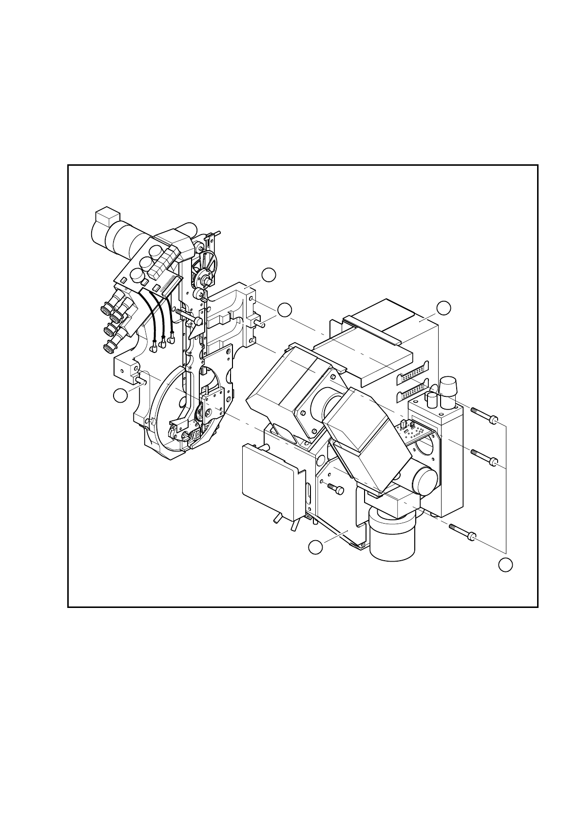
Fig. 9.13.1 Fitting the encoder housing to the lifting carriage housing
Key to Fig. 9.13.1
1 Cover 4 Lifting carriage housing
2 M4 fixing screws 5 Parallel pins
3 Encoder housing
1
3
4
5
5
2

9 Revolver Head SIPLACE 80S/F/G Service Manual
Edition 04/97
9 - 106