80S-15贴片机.pdf - 第161页
SIPLACE 80 S/ F/G Service M anual 6 PCB Handling Edition 01/96 6 - 25 6.5 Retainers and Compression Springs Spare parts, auxiliary materi als and equipment Retainer , rightha nd, Item No. 0031767 8-02 Retainer , leftha n…

6 PCB Handling SIPLACE 80 S/F/G Service Manual
Edition 01/96
6 - 24

SIPLACE 80 S/F/G Service Manual 6 PCB Handling
Edition 01/96
6 - 25
6.5 Retainers and Compression Springs
Spare parts, auxiliary materials and equipment
Retainer, righthand, Item No. 00317678-02
Retainer, lefthand, Item No. 00317679-02
Compression spring 0.8 * 8.8 * 32 V2A, Item No. 00200342-01 (order 2 for each conveyor side)
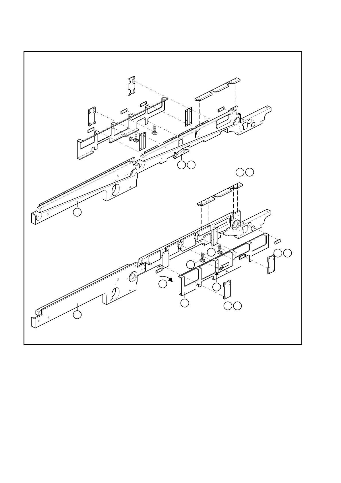
6.5.1 Removing retainers and compression springs
NOTE
OOO
You should also comply with the safety instructions in Chapter 1.
●
Adjust the board conveyor to the maximum width setting when you change the retainer on the fixed side of
the conveyor.
●
For board transport, select ’Half board conveyor width’ when you change the retainer on the movable side
of the conveyor.
●
Move the gantry or gantries to outside the board transportation area.
●
Lower the lifting table.
●
Switch off the machine at the main switch and disconnect it from the main power supply.
●
Make sure that the machine cannot be switched on while you are carrying out servicing work.
●
Remove the rocking lever (A).
●
Remove the three DU strips (B) and the two comb guides on the outside. To do so remove the M3
recessed-head screws and hexagon socket screws.
●
Undo and remove the M3 recessed-head screws which fasten the blocks (D) and remove the two com-
pression springs.
●
Remove the guide strip (E).
●
Swing the retainer outwards (F) and remove it.
6 PCB Handling SIPLACE 80 S/F/G Service Manual
Edition 01/96
6 - 26
Fig. 6.5.1 Removing the retainers and compression springs
Key to Fig. 6.5.1
1 Side panel, fixed side 2 Retainer
3 Comb guide 4 DU strips
5 Guide rail 6 Compression spring
7 Block 8 Rocking lever
9 Side panel, movable side
1
9
2
4 B
5 E
7
6
F
8 A
3 C
D