80S-15贴片机.pdf - 第227页
SIPLACE 80 S/ F/G Service M anual 7 Components Table Edition 04/97 7 - 45 DANGER QQQ Switch of f the machi ne at th e main switch a nd disc onnect it from the p ower supp ly. ● Pull ou t the p lug conn ections of both co…

7 Components Table SIPLACE 80 S/F/G Service Manual
Edition 04/97
7 - 44
7.6.9.3 Checking the Functioning of the New Motor
DANGER
OOO
When the SITEST program is used for the following work with the components changeover table moved out
(connected) there is an increased danger of accidents, particularly at the tape cutting unit, due to the cutter
wheel and cutter strip. Please observe the detailed DANGER note in section 7.6.2 on page 7 - 34!
●
Connect the components changeover table which has been moved out to the power supply (mains plug,
interface connector X37).
●
Connect the multimeter to the motor of the tape cutting unit, making sure the measuring cables are long
enough.
●
Position the multimeter so that you can read it easily during the activation which follows.
●
Switch on the machine and load the SITEST program.
●
Have a cutting stroke made. Select: "BE table"
→
"Single function"
→
"Tape cutter".
●
During the stroke, read the multimeter: If the cutter wheel pretensioning and the toothed belt tension are
correct you will read 2 - 2.5 A which is desired the power consumption.
●
The cutter wheel carriage must actuate the righthand limit switch and move back to the parking position.
–
If the motor now is activated, carry out the "Concluding work" (see section 7.6.15 "Concluding Work").
–
If the motor still does not activate, proceed, as described below.
–
The cutter wheel carriage must not hit against the buffer (replace clamping connector, if necessary).
7.6.9.4 Checking the Cable Y559-W1 for Breaks
●
Quit the SITEST program and switch the machine off at the main switch.
GEFAHR
QQQ
Switch off the machine at the main switch and disconnect it from the power supply.
●
To check the cable for breaks proceed now as described in section 7.5 "Communications Unit".
–
In the event of a fault replace the cable Y559-W1 as described in section 7.5 "Communications Unit".
–
If, however, there is nothing wrong with the cable Y559-W1, continue fault location as follows.
7.6.9.5 Determining whether the Communications Unit or the Flap Opener Control-
ler is Defective
The + 30 VDC voltage and the signal for the tape cutter are routed as follows:
processor board, plug X5
→
"Flap opener control" board (IC)
→
processor board, plug X4 (see circuit dia-
grams folder, circuit diagrams 1710460- Y0031-...-L-..., Sh. 3 and -Y0014-...-L-.., Sh. 1).
–
You can quickly narrow down the location of the break by connection to an intact communications unit
(replacement of the components changeover tables). The procedure in detail is as follows:
●
Quit the SITEST program and switch the machine off at the main switch.

SIPLACE 80 S/F/G Service Manual 7 Components Table
Edition 04/97
7 - 45
DANGER
QQQ
Switch off the machine at the main switch and disconnect it from the power supply.
●
Pull out the plug connections of both components changeover tables (interface connector X37, mains plug
and, if applicable, pneumatics connection), in each case on the righthand side of the machine base.
●
Remove the components changeover tables: See section 7.6.2.2 "Checking the Limit Switch and Cable
Y637, Y638".
●
Connect the changeover tables in reversed position in each case on the righthand side of the machine
base.
●
Please note with the following work the DANGER notice above: danger of physical injury!
●
Switch the machine on, load the SITEST program and select:
"BE table"
→
"Single function"
→
"Tape cutter".
●
Check now the motor activation:
–
If the motor is now activated, there is an interruption on the processor board of the associated commu-
nications unit or in the components table interface cable Y559-W1.
Check the cable Y559, replace the cable or the communications unit as described in section 7.5
"Communications Unit".
–
If the motor is now not activated, replace the "Flap opener complete" as described in section 7.4 "Flap
Opener (Magazine Openers)". The board "Flap opener control" cannot be replaced alone as it is not a
spare part.
●
When refitting the empty tape channel align it with the pressure rod (see section 7.6.12 "Swivel Mecha-
nism").
●
Carry out the "Concluding work" (see section 7.6.15 „Concluding Work“ on page 7 - 55).
7.6.10 Checking, Replacing and Tensioning the Cut Toothed Belt at the
Cutter Wheel
If the cut toothed belt is damaged or incorrectly tensioned, this can be the cause of the motor being switched
out, premature wear or the tapes not being cut.
●
If you have not yet done so, select "Abort placement"
DANGER
QQQ
Switch off the machine at the main switch and disconnect it from the power supply.
●
Remove the components changeover table. To do so, carry out all steps as described in the section
7.6.2.2 "Checking the Limit Switch and Cable Y637, Y638". Pay attention to the placement head!
●
Remove the empty tape cutting unit (see "Replacing the cutter wheel and cutter strip ...").
●
Unscrew and remove the two tension pieces (see Fig. 7.6.4) and thread out the toothed belt.
●
Fit the new toothed belt in the reverse sequence of operations, first fastening the tension pieces so that the
toothed belt is at "normal" tension.
7 Components Table SIPLACE 80 S/F/G Service Manual
Edition 04/97
7 - 46
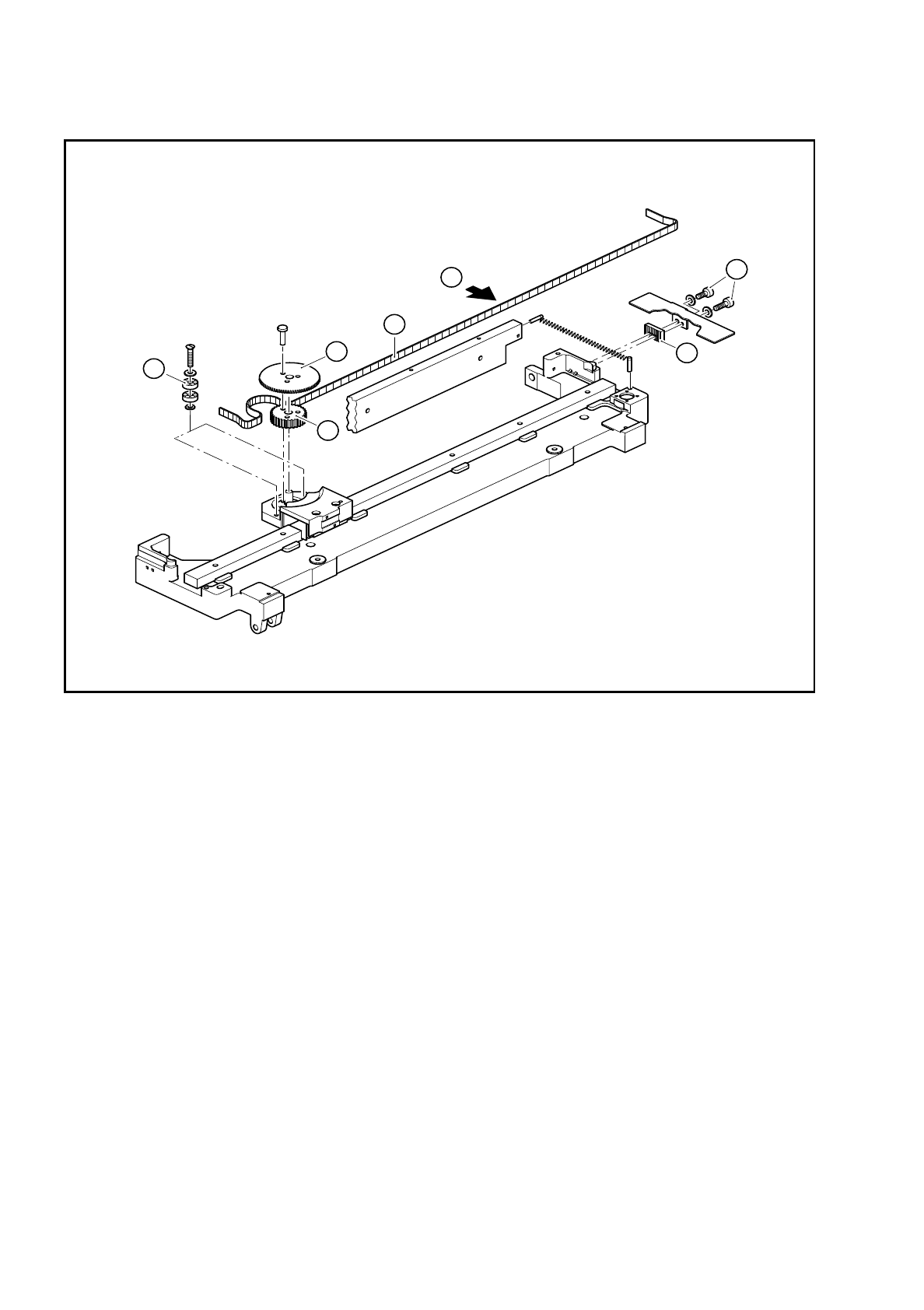
Fig. 7.6.4 Replacing and tensioning the cut toothed belt
Key to Fig. 7.6.4
1 Cut toothed belt
2 Cutting wheel
3 Deflection pulley
4 Synchronizing disk
5 Clamping piece
6 2 Hexagon socket-head cap screws M4
A Measure the belt tension in the middle of the belt, setpoint value 40-45 Hz
4
2
3
1
6
5
A