80S-15贴片机.pdf - 第243页
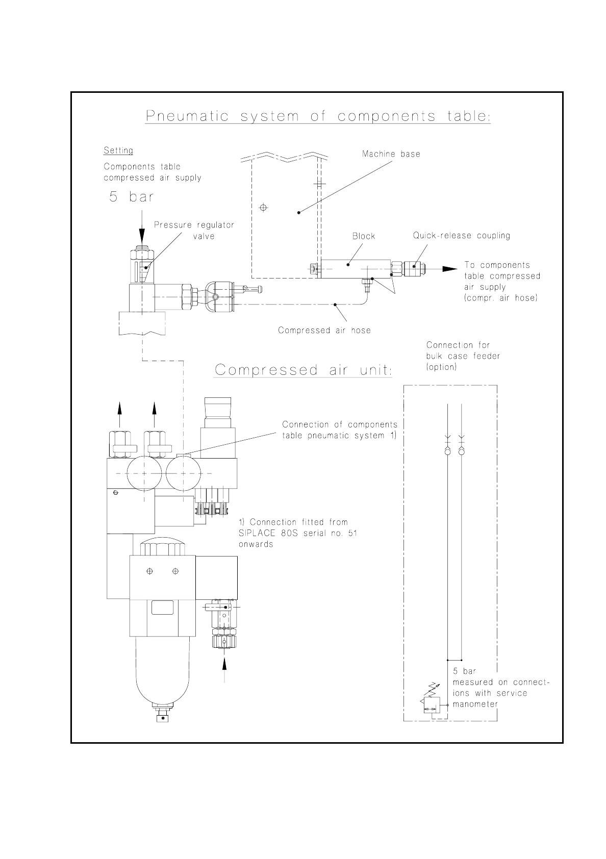
SIPLACE 80 S/ F/G Service M anual 7 Components Table Edition 04/97 7 - 61 Fig. 7. 7.1 Testing the compressed air branch o f the "Compressed air unit - components table pneum atic system"

7 Components Table SIPLACE 80 S/F/G Service Manual
Edition 04/97
7 - 60
●
If necessary, check the compressed air hose which runs in the interior of the machine base. If the
compressed air hose is pinched, replace it. Fit the cable lacings back in place, reconnect the
compressed air hose to the block and to the components table compressed air supply.
●
Connect the machine to the mains and switch on.
●
Fit the cover to the machine base (size 3 screwdriver for socket-head screws).
●
If you still have not been able to determine what the fault it, check the components table compressed air
supply unit.
SIPLACE 80 S/F/G Service Manual 7 Components Table
Edition 04/97
7 - 61
Fig. 7.7.1 Testing the compressed air branch of the "Compressed air unit - components table pneumatic system"
7 Components Table SIPLACE 80 S/F/G Service Manual
Edition 04/97
7 - 62
7.7.3.1 Fault Location and Correction: Components Table Compressed Air Supply
●
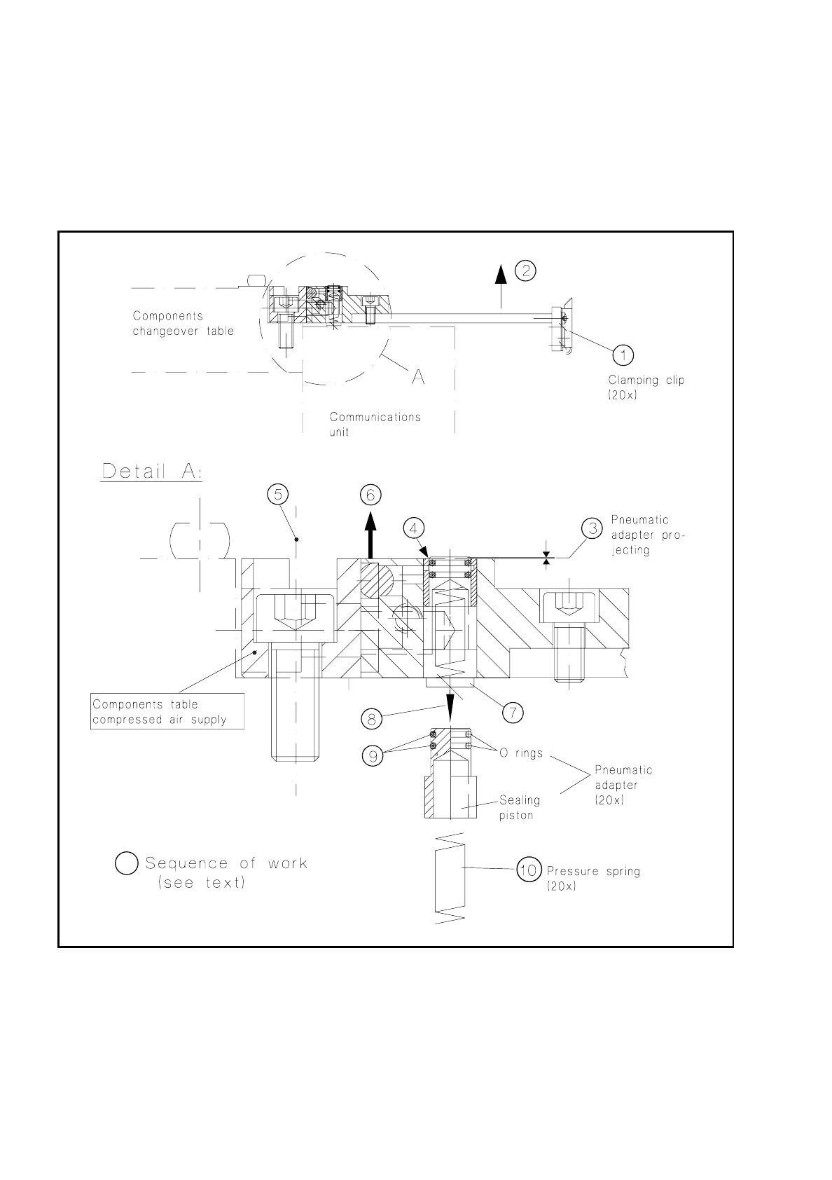
Check the clamping clip of (see Fig. 7.7.2, Item 1) of the module which is not conveying properly. It must
be correctly closed and press the module correctly against the support strip. If necessary, replace the
clamping clip (undo 2 countersunk screws M3).
Fig. 7.7.2 Components table compressed air supply: checking and replacing o-rings and pressure springs of the pneumatic adapters
●
If this does not correct the fault, switch off the machine at the main switch and slide the corresponding
placement head by hand into the area within the PCB conveyor to prevent the head being damaged when
the modules are subsequently removed.
Note: You must observe a minimum clearance here of the x gantry axes - the axis must not be at the crash
switch (see User’s Manual, Section 9, subsection "Empty tape cutting device".